
Light switch and Marderschreck with ATtiny15
This is a 2-in1 project, it contains a night light switch with a bit of intelligence and an ultrasonic soundgenerator to chase the vermin out of the garden. Both are quite independent from each other, so one or the other version can be built or a combination of both.
Let's first look at the night light switch. One LDR monitors the light as usual, however I found that LDR's change their resistance value over time, especially when they are mounted outside. With a fixed threshold it means the light is turned on too early or too late. With a microcontroller we can calculate a dynamic threshold and get a more adaptive light switch which can handle changing conditions. See the example below to see how it's done.
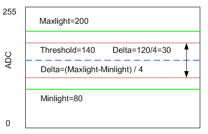
The ADC is using 8-bit resolution 0 to 255 to digitize the light values. The program stores the extreme light values of every day and night, this gives Maxlight and Minlight (the green lines) and from these values it calculates the average threshold (the blue dotted line): (Maxlight + Minlight)/2. Now we need more hysteresis therefore a Delta is calculated which is Maxlight - Minlight divided by 4 to make it easy. 120 in this case div 4 = 30. The Delta of 30 is added to Threshold to give the upper value or substacted to give the lower value, the red lines above. Above or below the light is switched on or off. Finally we have an adaptive Threshold and a Delta in a light switch, looks like a clear overkill.
There is another hysteresis in the program, a time hysteresis. When e.g. dark is recognized it waits some time before it finally switches. This can be changed in the program: Nightdelay = 15 means wait and check light 15 seconds before switch night light on or off. It helps when we have very slowly changing light conditions. Another time limit is LightOntime = 14 , the hours light is turned on. Could be changed to 6 if you want light only 6 hours after dark and then switch off. A flag in the program remembers that light-on is done already even if it is still night, a new cycle is started with the new daylight and the flag is reset.
It might be nice to calculate a moving average for Maxlight and Minlight to
adapt to the changing light in different seasons. I leave this to your ingenuity,
otherwise it's enough to do a reset once in a while and the microcontroller
will establish new values.
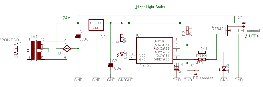
The circuit digram of a version I've used to light my staircase at night, one led per step, 7 in a row and 21 in total. That's why it's called Stairs2.asm.
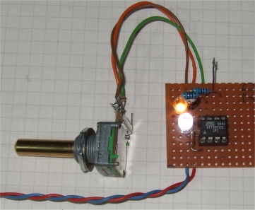
The test assembly to check the thresholds, uses a potentiometer instead of a LDR.
Marderschreck version
I have build different versions and they all worked quite well. Below is the Marderschreck version which is using the ultrasonic sound generator with a TDA2030 as a power amplifier, this amp has a power bandwidth from 10 to 140000 Hz. It needs a good piezo speaker and will make terrible noise, ultrasonic.
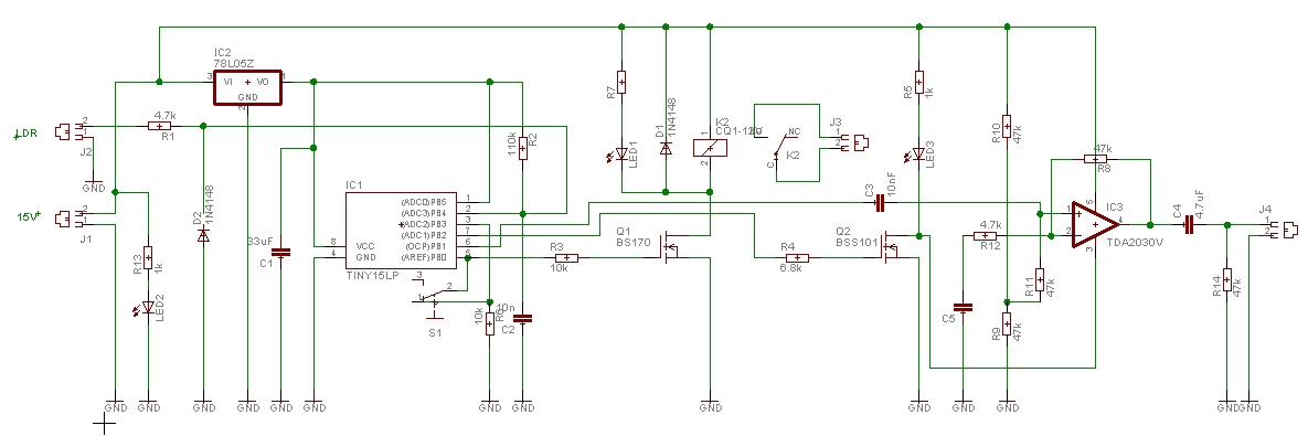
The circuit digram of a version with ultrasonic output and a relais to switch a light. S1 can switch the sound off or to automatic on at night.
I don't know the exact ultrasonic frequency which sounds nasty to vermins so there is a frequency sweep between about 20 and 40 kHz. This is done with Timer1 in pwm mode and OC1A on PB1 is the frequency output. It cycles through SweepUp and SweepDown and a pseodorandom sweep, maybe one frequency will finally work. The program uses Ontime = 40 which means 40 seconds sweep sound out and then Offtime = 180 means 180 seconds = 3 min quiet time. So it switches on and off, if the beasts think they can return they get a nasty surprise three minutes later.
In a car's Marderschreck there is no need to use the LDR, just the Atiny15 and a power amplifier like TDA2030 and a piezo speaker will do. A low level at input PB3 turns the sound off and a high level turns it on. PB1 is the ultrasonic frequency output. Connect PB3 to high and PB1 to the input of the power amplifier.
Well, the program might be a bit complex for a simple light switch but it was
fun to see that it finally worked. It started as two different programs but
then there was enough space in the flash memory of the Atiny15 and I joined
the two. So it is a 2-in-1 project and one or the other part might be fine for
your application.
download Stairs2.asm
This program is distributed in the hope that it will be useful but WITHOUT
ANY WARRANTY;
References
datasheet ATtiny15, Atmel.com
datasheet TDA2030, STMicroelectronics
Gerd's AVR assembler version 2.7: http://www.avr-asm-tutorial.net/gavrasm/index_en.html
;***************************************************************************
; AT15  Stairs light based on Nlite2
;	night light switch using LDR to sense light
;	and Marderschreck pwm frequency sweep ultrasonic output 20-40kHz
;
;	night light switch reading LDR on ADC3, fixed on-time
;	light turns off after on-time elapsed or day
;	light threshhold is calculated
;	DayLow PB2 shows night (hi) or day (lo)
; 	ATtiny15 GS 07-2011, ok
;	The timing is adapted for 1.6 MHz
;
;  This program is free software; you can redistribute it and/or
;  modify it under the terms of the GNU General Public License.
;  This program is distributed in the hope that it will be useful,
;  but WITHOUT ANY WARRANTY;
;
;***************************************************************************
;			ATtiny15 dip
;	(RESET/ADC0) 	PB5	VCC
;	(ADC3) 		PB4	PB2 (ADC1/SCK/T0/INT0)
;	(ADC2) 		PB3	PB1 (AIN1/MISO/OC1A)
;			GND	PB0 (AIN0/AREF/MOSI)
;
;***************************************************************************
; PB4	input 	LDRin +5V - R1 - PB4 - LDR - Gnd
; PB3	input	switch hi ultrasonic sound on, lo sound off (wire to PB0)
; PB2	output	shows night (hi) or day (lo)
; PB1	output	OC1A pwm frequency ultrasonic out
; PB0	output	Nightout act hi, switch light
;***************************************************************************
; Flag, 0b10000111
; bit7 LDRin: lo = day hi = night, threshold
; bit2 sound done flag
; bit1 light done flag
; bit0 LDRin: lo = day, hi = night after delay

.DEVICE ATtiny15	;for gavrasm


.equ	reload		= 256 - 250	; 40 us x 250 = 10 ms Timer0
.equ	waittime	= 2		; wait x 10 ms Timer0 for sound
.equ	Ontime		= 40		; 40  seconds sweep sound out
.equ	Offtime		= 180		; 180 seconds = 3 min quiet time

.equ 	maxpwm		= 170		; 159 = 20kHz Timer1 pwm (18.8 kHz)
.equ 	minpwm		= 80		;  80 = 40kHz @ pck/8
.equ 	dutypwm		= maxpwm/2	; duty cycle
.equ	T1_on		= 0b01100100	; Timer/Counter 1 pwm pck / 8 = 0.3128us
.equ	T1_off		= 0

.equ	center		= 127		; ADC center
.equ	Nightdelay	= 15		; wait 15 seconds before switch night light on or off
;.equ	LightWttime	= 30		; minutes wait before light is turned on
.equ	LightOntime	= 14		; max hours light is turned on

;***************************************************************************
; Port Definitions
;***************************************************************************

.equ	Nightout	= PB0		; night detect out act hi
					; PB1 pwm out
.equ	DayLow		= PB2		; output DayLow
;.equ	signal		= PB2		; output signal hi when sweep on
.equ	sndpin		= PB3		; input	 switch hi sweep, lo off
.equ	LDRin		= PB4		; night detect, +5V - R1 - PB4 - LDR - Gnd

;***************************************************************************
; Register Definitions
;***************************************************************************

.def 	deltalight	= r8
.def 	avglight	= r9
.def	ADClight	= r10
.def	Minlight	= r11
.def	Maxlight	= r12
.def	LightThresh	= r13
.def	Sr		= r14
.def	T0reload	= r15

.def	temp		= r16
.def 	countL		= r17	; main timing
.def	countSec	= r18
.def 	cntLight	= r19	; night light timing
.def	Flag		= r20	; day or night

.def 	counter		= r21
.def	topcount	= r22
.def	dutycyc		= r23
.def	second  	= r24
.def	minute		= r25
.def	hour		= r26
.def	itemp		= r27
;.def	ZL		= r30
;.def	ZH		= r31


.cseg
.org 0
; Reset-vector to adress 0000
	rjmp	reset
	reti 			; INT0addr= 0x0001 External Interrupt 0
	reti 			; PCI0addr= 0x0002 Pin Interrupt Request
	reti 			; OC1addr=  0x0003 Timer/Counter1 Compare Match
	reti 			; OVF1addr= 0x0004 Timer/Counter1 Overflow
	rjmp	TIM0_OVF	; OVF0addr= 0x0005 Timer/Counter0 Overflow
	reti 			; ERDYaddr= 0x0006 EEPROM Ready
	reti 			; ACIaddr=  0x0007 Analog Comparator
	reti 			; ADCCaddr= 0x0008 ADC Conversion Ready

;***************************************************************************
;* "TIM0_OVF" - Timer/counter0 overflow interrupt handler
;*
;* The overflow interrupts every 10 ms
;*
;***************************************************************************

TIM0_OVF:	in	Sr,sreg			; Updated every 10 ms, calibrate

		out	TCNT0,T0reload		; for 10 ms Interrupt

		;sbis	PINB, DayLow		; skip if set
		;sbi	PORTB, DayLow		; set output
		;sbic	PINB, DayLow	 	; skip if set
		;cbi	PORTB, DayLow

		inc	counter			; wait timing
		inc	countL			; main timing
		cpi	CountL, 100		; 100 x 10 ms
		breq	TIM0_1s
		rjmp	TIM0_ex
TIM0_1s:	clr	countL			; every second
		inc	countSec		; seconds 0 to 255

		inc	second			; 24 hr counters
		cpi	second,60
		brne	TIM0go
		clr	second
		inc 	minute
		cpi	minute,60
		brne	TIM0go
		clr	minute
		inc 	hour
		cpi	hour,24
		brne	TIM0go
		clr	hour

TIM0go:						; every second ->get ADC value	PB4 ADC3 sensor LDR light
		ldi	itemp,0b11010011 	; ADC init single conversion presc 8:
		out 	ADCSR, itemp
TIM0wait:           				; again
		sbis 	ADCSR, ADIF
		rjmp 	TIM0wait
		in 	ADClight, ADCH 		; high byte only, ADLAR=1
		add	avglight, ADClight	; lo is day
		ror	avglight		; /2

		cp  	Minlight, avglight	; store Minlight, compare lo is day
		brsh	TIM0mm1
		mov	Minlight, avglight	; is lower
TIM0mm1:	cp  	Maxlight, avglight	; compare hi is night
		brlo	TIM0mm2
		mov	Maxlight, avglight	; is higer, store Maxlight
TIM0mm2:
		mov	LightThresh, Maxlight	; calculate average thresh
		add	LightThresh, Minlight	; (max + min)/2
		ror	LightThresh		; /2

		mov	deltalight, Maxlight	; max - min
		sub	deltalight, Minlight	; calculate delta
		lsr	deltalight		; 25 % of max - min
		lsr	deltalight		; /4
		;lsr	deltalight		; /8

		mov 	itemp, LightThresh	; lower threshold - delta
		sub	itemp, deltalight
		cp  	avglight,  itemp	; compare thresh - deltalight
		brsh 	TIM0c1			; higher
		cbr	Flag,0b10000000		; is lower, set day flag, i.e. clear bit7
		cbi	PORTB, DayLow		; test---------------------------------------------
		rjmp	TIM0chk
						;
TIM0c1:		mov 	itemp, LightThresh	; high threshold + delta
		add	itemp, deltalight
		cp  	avglight,  itemp	; compare
		brsh 	TIM0c2			; is same or higher ?
		rjmp	TIM0chk			; no, do nothing
TIM0c2:		ori	Flag,0b10000000		; is higher, set nite flag, i.e. set bit7
		sbi	PORTB, DayLow
		;rjmp	TIM0chk

						; check light every second
TIM0chk:	sbrs	Flag, 7			; skip if Flag hi, night
		inc 	cntLight		; Flag lo is day
		cpi	cntLight, Nightdelay	; 15 sec day
		brsh	TIM0day
		sbrc	Flag, 7			; skip if Flag lo, day
		inc 	cntLight		; lo Flag is day
		cpi	cntLight, Nightdelay	; 15 sec nite
		brsh	TIM0nite
		rjmp	TIM0_ex
TIM0nite:
		sbrc	Flag,0
		rjmp	TIM0n1
		clr	second			; counters zero once every night
		clr	minute
		clr	hour
TIM0n1:
		sbr 	Flag, 0b00000001	; bit0 set LDRin is lo, high = night
		clr 	cntLight
		;sbi	PORTB, Nightout
		rjmp	TIM0_ex

TIM0day:
		cbr 	Flag, 0b10000011	; bit reset LDRin lo = day
		clr 	cntLight


TIM0_ex:	out	sreg,Sr
		reti


;***************************************************************************
;*		Reset
;***************************************************************************

reset:
		; writing the calibration byte to the OSCCAL Register.
		ldi	temp,0x75    		; test , config val
		out	OSCCAL,temp 		; for the clock
		nop
		nop

		ldi	temp,0b00001000 	; set pullup
		out	PORTB,	temp		; 1 = pull-up , 0 = float
		ldi	temp,0b00000111 	; output, 1 = output , 0 = input
		out	DDRB,temp       	; to data direction register

;***************************************************************************
; AD-Converter setup:
		; ADMUX: REFS1 REFS0 ADLAR – – MUX2 MUX1 MUX0
		; If ADLAR is set, the result is left-adjusted. 8 bit
		ldi 	temp, 0b00100011  	; Ch 3 input=PB4, REFS0,1 =0 Vcc is RefVoltage0
		out 	ADMUX, temp

		; ADCSR: ADEN ADSC ADFR ADIF ADIE ADPS2 ADPS1 ADPS0
		ldi	temp,0b11010011 	; ADC init single conversion presc 8:
		out 	ADCSR, temp
; timer1 setup:

		ldi	temp,maxpwm		; Timer/Counter 1 top count
		out	OCR1B,temp		;
		ldi	temp,dutypwm		; Timer/Counter 1 compare val
		out	OCR1A,temp		;
		;ldi	temp,0b01100100		; Timer/Counter 1 pwm pck / 8 = 0.3128us
		ldi	temp,T1_off		; Timer/Counter 1 stop count
		out	TCCR1,temp		;

; timer0 setup:
		ldi	temp,0b00000010		; Bit 1 – TOIE0: Timer/Counter0 Overflow Interrupt Enable
		out	TIFR,temp 		; clear pending Interrupt
		out	TIMSK,temp 		; in the Timer Interupt Mask Register

		ldi	temp,0b00000011 	; Timer/Counter 0 clocked at CK/64 = 40 us
		out	TCCR0,temp		; 1,6 Mhz
		ldi	temp, reload		; Timer/Counter 0 reload
		out	TCNT0,temp		; for 10 ms Interrupt

;***************************************************************************
		mov	T0reload, temp
		clr	Flag
		ldi	temp, center		; center
		mov	avglight,temp 		; to start
		mov	LightThresh,temp 	; to start
		ldi	temp, center-10		; < center
		mov	Minlight,temp		; Minlight
		ldi	temp, center+10		; > center
		mov	Maxlight,temp

		sei				; Enable gobal interrupt

;***************************************************************************
; main loop
; PB3	input	switch hi ultrasonic sweep on, lo sweep off,
; connect to Nightout pin for automatic on at night or use switch


lightloop:
		sbrs	Flag,0
		rjmp	lightday		; flag lo, day
		;rjmp	lightnite		; flag hi, night

		sbrc	Flag,1			; if 0 light not done
		rjmp	sndloop			; flag hi, light done, check sndloop
		;cpi	minute, LightWttime	; fixed Light wait time before turn on
		;brlo	sndloop
		sbi	PORTB, Nightout
		cpi	hour, LightOntime	; fixed LightOntime in hours
		brlo	sndloop
		sbr	Flag, 0b00000010	; light done, set flag
lightday:
		cbi	PORTB, Nightout		; day or done: turn light off

sndloop:	sbis	PINB, sndpin		; skip if sndpin high
		rjmp	sndpinlo		; switch lo, sweep off
		rjmp	sndpinhi		; switch hi, sweep on
sndpinlo:
		rjmp	lightloop		; goto lightloop

sndpinhi:
		sbrc	Flag,2			; if 0 not done
		rjmp	waitoff			; if 1 then wait Offtime
		ldi	temp,T1_on		; Timer/Counter 1 start pwm
		out	TCCR1,temp		;
		;sbi	PORTB, signal		; signal on when sound on
		nop				; turn on amplifier, may need more delay
		clr	countSec
soundout:
		rcall 	SweepUp			; abt 14.4 sec for 1 loop
		rcall 	SweepDown
		rcall	Random
		rcall 	SweepUp
		rcall 	SweepUp
		rcall	Random
		rcall 	SweepDown
		rcall 	SweepDown

		cpi	countSec, Ontime
		brlo	soundout

		ldi	temp,T1_off		; Timer/Counter 1 stop
		out	TCCR1,temp		; sound off
		;cbi	PORTB, signal		; signal off, turn off amplifier
		sbr	Flag, 0b00000100 	; sound done

		clr	countSec
waitoff:
		cpi	countSec, Offtime	; wait Offtime
		brlo	lightloop
		cbr	Flag, 0b00000100 	; sound not done, can do again

		rjmp	lightloop			; loop

;***************************************************************************
;*		Subroutines
;***************************************************************************

SweepDown:	clr	counter
		ldi 	topcount, minpwm	; 40 kHz
		out	OCR1B, topcount		; top count

loopdn:		cpi	counter, waittime	; reaction time
		brlo	loopdn
		clr	counter

		out	OCR1B, topcount		; top count
		mov	dutycyc, topcount
		lsr	dutycyc			; / 2 = 50 % duty cycle
		out	OCR1A, dutycyc		;
		inc	topcount		; decrease frequency
		cpi	topcount, maxpwm	; 20 kHz
		brlo	loopdn
		ret


SweepUp:	clr	counter

		ldi 	topcount, maxpwm	; 20 kHz
		out	OCR1B, topcount		; top count

loopup:		cpi	counter, waittime	; reaction time
		brlo	loopup
		clr	counter

		out	OCR1B, topcount		; top count
		mov	dutycyc, topcount
		lsr	dutycyc			; / 2 = 50 % duty cycle
		out	OCR1A, dutycyc		;
		dec	topcount		; increase frequency
		cpi	topcount, minpwm	; 40 kHz
		brsh	loopup
		ret

Random:
		ldi	ZL, (2*TIM0_OVF)	; use flash for pseudo random
		clr	counter

looprnd:	cpi	counter, waittime	; reaction time
		brlo	looprnd
		clr	counter

		lpm
		mov	topcount, r0
		andi	topcount, 0x7F		; limit to 127
		subi	topcount, -minpwm	; add minpwm 80, 207 = 15.4 kHz
		out	OCR1B, topcount		; top count
		lsr	topcount		; / 2 = 50 % duty cycle
		out	OCR1A, topcount		;
		inc	ZL
		cpi	ZL, 99			; 90 values (start at 0x09)
		brlo	looprnd
		ret