
Measure Temperature with DS1620 and ATtiny2313
There are many thermometer projects on the web and shops sell them at low prices, so why build another one?
The DS1620 can measure temperature over the range of -55 C to +125 C with 0.5
C resolution. However, if we want to use the DS1620 stand-alone we first need
a way to program the device and set TH and TL to the temperature we want. This
is the reason for this little project. In addition it displays the temperature
on 3 digit 7-segment display. It has a serial interface which allows programming
of the DS1620 and we can also record and plot the temperature on a PC. The temperature
reading is send automatically every second or on request. The program is written
in assembler and compiled with gavrasm.
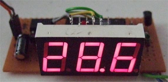
Front view of the thermometer (on a normal day in Asia)
The data from DS1620 is transmitted serially through a 3–wire serial interface to the ATtiny2313. Here the ATtiny2313 acts as a translator between DS1620 and the RS232 interface to the PC. Below is a list of commands: (no need to hit return)
| RS232 commands: | ||
| command from PC | description | reply received |
| t | read temperature | T+02863 |
| r | read stored TH and TL | H=001E |
| L | write TL: send e.g. L00 | |
| H | write TH: send H15 | |
| c | read DS1620 Config | C=CB |
| d | Write Config to default settings CPU=0, 1SHOT=0 | |
| 0 | 0 = no auto send temperature (RS232) | |
| 1 | 1 = auto send temperature every second (default) |
Note that temperature is represented in the DS1620 in terms of a ½ C LSB, resulting in a 9–bit format. Command 'r' returns TH / TL as hex temperature * 2 because of the 9–bit format. H=001E hex is 30 decimal meaning 15 degrees is set. It' not a bug, it's a feature. When you send H15 the program will multiply 15 * 2 and program the DS1620 with 15 degrees for TH. Living in a warm country I have not implemented programming of temperatures below zero, L00 is the lowest temperature which can be programmed. Feel free to change this.
The 't' command returns the temperature in degrees Celsius, T+02863 means +28.63
C. Temperatures below zero are shown on the display like temperatures above
zero, in addition PD6 goes to a low level and could be used to turn on a blue
led. The 't' command would reply with e.g. T-01726 on RS232.
From the datasheet we see that the DS1620 provides 9–bit temperature readings which indicate the temperature of the device. With three thermal alarm outputs, the DS1620 can also act as a thermostat. THIGH is driven high if the DS1620’s temperature is greater than or equal to a user–defined temperature TH. TLOW is driven high if the DS1620’s temperature is less than or equal to a user–defined temperature TL. TCOM is driven high when the temperature exceeds TH and stays high until the temperature falls below that of TL. Nice to have a good hysteresis here. The idea is to program the device first and set TH and TL, then use it stand alone, e. g. to turn on a led when the temperature is below freezing, send L00 in this case. Below is the DS1620 pin assignment:
| DS1620S | 8-Pin | PDIP | |
| DQ | 1 | 8 | VDD |
| CLK/CONV | 2 | 7 | THIGH |
| RST | 3 | 6 | TLOW |
| GND | 4 | 5 | TCOM |
Noname 3-digit common anode displays are used here. You may find similar ones but with other displays the program will need some adjustment for the different pin assignment of the display. Easy to do but that's why the circuit digram below is a bit sketchy regarding the display. No Quartz is used so the XTAL1/2 are normal output to the display digits, dig1 = PA1, dig2 = PA0, dig3 = PD2. The 220 Ohm resistors are wired from PORTB to the nearest pin of the display, which results in segments B G C dp D E F A to PORT 7-0. In the program is a translation table to handle this situation, you should adjust this for your display.
There is no need to install the display if you want to program the DS1620 only. If you want to show the temperature only the RS232 parts can be omitted.
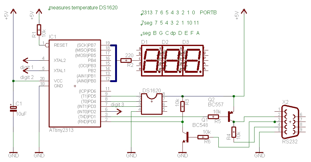
Circuit diagram of the thermometer.
The RS232 interface is using just 2 transistors instead of the usual MAX232 to save parts costs and space on the board. Here the collector of Q2 is connected to pin 4 of the plug which means your terminal program has to turn on DTR -Data Terminal Ready- in order to receive data. It depends on the PC's serial interface, in some cases it may be enough to connect R4 to GND but you have to try first and check if the PC can receive data. This is why auto send is on by default. Baudrate is 9600,8,N,1. If you can't send or receive any data or get garbage the clock frequency might be too far away. The program uses the 4 MHz internal oscillator ( unprogram CKDIV8 fuse and write CKSEL3..0 to 0011 ) and the baudrate is derived from the clock. Check the signal on one of the digit pins, e.g. PD2, it should be close to 2ms high on a scope. Otherwise change the OSCCAL register in the reset routine, a bit of trial and error, until the internal oscillator is calibrated.
PD6 is used in to indicate temperatures below zero. PD6 goes low below zero degrees and high above. It will also send the temperature as T+02863 or T-01726 (in my freezer). Below is a proposal to show if it is below zero or above, below the blue led is on, above the white. It' a trick to use 2 leds on 1 I/O pin and I have used it before on devices with few I/O pins. It can show 3 states: blue, white, and both off if you make the pin an input in the data direction register, not done here. Looks a bit like charlieplexing leds.
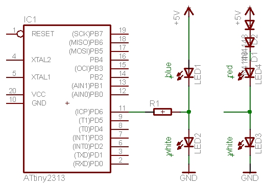
Part of the circuit diagram to show temperatures below zero or above on PD6
Here you see how it could be built on a simple perf board. No leds used here.
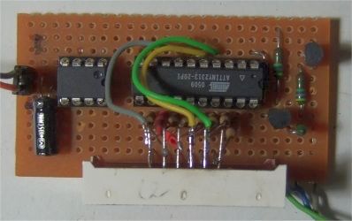
Top view of the thermometer, on the left is DS1620 on a socket and it can be removed once it is programmed.
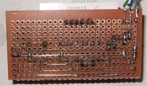
Bottom view, shows the wiring, upper right is the RS232 connection to the PC.
Once the DS1620 is programmed it can be used in continuous mode as a simple thermostat, no microcontroller is required. Don't forget to write Config to default settings CPU=0, 1SHOT=0 (command d) before using it stand-alone.
It can control a heater for your yoghurt maker or the cooling fan in a PC which is turned on when the temperature is above TH. It's recommended to read the DS1620 datasheet to get some ideas.
Otherwise it's just nice to have a thermometer which you can see in the dark.
download DS1620_5.asm
This program is distributed in the hope that it will be useful but WITHOUT
ANY WARRANTY;
References
datasheet DS1620, Maxim, www.maxim-ic.com
datasheet ATtiny2313, Atmel.com
displays with same pins e. g. at https://www.lc-led.com/View/itemNumber/233
DS1620 subroutines by Mathias Dzionsko (madz@gmx.de)
Gerd's AVR assembler version 2.7: http://www.avr-asm-tutorial.net/gavrasm/index_en.html
;***************************************************************************
;
; ATiny2313 and DS1620
;
; displays temperature on 3 dig 7-seg display
; useful to program DS1620 TL & TH for stand alone measurements
;
; measure temperature with DS1620 and send result every second (default)
; RS232 commands, see below
;
; unprogram CKDIV8 fuse and write CKSEL3..0 to 0011
; calibrate 4MHz internal osc, check PD2, should be 2ms high
; PD6 used to indicate temperature below zero
; GS June 2010-2012
;
; This program is free software; you can redistribute it and/or
; modify it under the terms of the GNU General Public License.
; This program is distributed in the hope that it will be useful,
; but WITHOUT ANY WARRANTY;
;
;***************************************************************************
;
; display 3 digits
; 7 seg digits on PORTD & A, segments on PORTB
; uses 3 digit common anode 7 seg display, see below
;
; pin 12 11 10 09 08 07
; |------------------------------|
; | d1 A F d2 d3 B | |--A--|
; | | F B
; | top view | |--G--|
; | | E C
; | E D dp C G nc. | |--D--|.dp
; |------------------------------|
; pin 01 02 03 04 05 06
;
; 2313 7 6 5 4 3 2 1 0 PORTB
; 7seg 7 5 4 3 2 1 10 11 pin 12 9 8
; seg B G C dp D E F A dig 1 2 3 (3 = right dig)
;
;***************************************************************************
; ATiny2313 PDIP
;
; (RESET/dW) PA2 1 20 VCC
; (RXD) PD0 2 19 PB7 (UCSK/SCK/PCINT7)
; (TXD) PD1 3 18 PB6 (MISO/DO/PCINT6)
; (XTAL2) PA1 4 17 PB5 (MOSI/DI/SDA/PCINT5)
; (XTAL1) PA0 5 16 PB4 (OC1B/PCINT4)
; (CKOUT/XCK/INT0)PD2 6 15 PB3 (OC1A/PCINT3)
; (INT1) PD3 7 14 PB2 (OC0A/PCINT2)
; (T0) PD4 8 13 PB1 (AIN1/PCINT1)
; (OC0B/T1) PD5 9 12 PB0 (AIN0/PCINT0)
; GND 10 11 PD6 (ICP)
;***************************************************************************
;
; DS1620S 8-Pin PDIP
;
; DQ 1 8 VDD
; CLK/CONV 2 7 THIGH
; RST 3 6 TLOW
; GND 4 5 TCOM
;***************************************************************************
; (front view) Serial Port
;
; 9 pin serial port (male): 9 pin serial port (female):
;
; Pin 1 5 Pin 5 1
; _____________ _____________
; \ . . . . . / \ . . . . . /
; \ . . . . / \ . . . . /
; \_______/ \_______/
; Pin 6 9 Pin 9 6
;
; Pin Description
; 1 CD Carrier Detect Input
; 2 RXD Receive Data Input
; 3 TXD Transmit Data Output
; 4 DTR Data Terminal Ready Output
; 5 Signal ground
; 6 DSR Data Set Ready Input
; 7 RTS Request To Send Output
; 8 CTS Clear To Send Input
; 9 RI Ring Indicator Input
;
;***************************************************************************
;
; RS232 commands:
; t ; read temperature => T+02543<cr><lf>
; r ; read stored TH and TL => H=001E<cr><lf>L=0000<cr><lf>
; L ; write TL: send e.g. L25
; H ; write TH: send H30
; c ; read DS1620 Config => C=CB<cr><lf>
; d ; Write Config to default settings CPU=0, 1SHOT=0
; 0 ; 0 = no auto send temperature (RS232)
; 1 ; 1 = auto send temperature every second (default)
;
; (r returns TH / TL as hex temperature * 2, H=001E hex = 30 dec => 15 degrees is set)
;
; DS1620 subroutines by : Mathias Dzionsko (madz@gmx.de)
;
; DS1620Setup
; DS1620ReadCfg
; DS1620WriteCfg
; DS1620Start
; DS1620Stop
; DS1620ReadTemp
; DS1620ReadTemp100, GS mod for T<0
; DS1620ReadCounter
; DS1620ReadSlope
; DS1620WriteTH
; DS1620WriteTL
; DS1620ReadTH
; DS1620ReadTL
.DEVICE ATtiny2313 ;compiled with gavrasm
.equ clock = 4000000
; more Definitions
.equ baudrate = 9600
.equ baudval = clock/(16*baudrate)-1
.equ c_value = 8000-1 ; Compare value for output compare interrupt
; 8000 cycles@4Mhz = 2ms
.equ plusminus = PIND6 ; T < 0 is low, > 0 is high
.equ DS1620_DDR = DDRD ; DS1620 definitions
.equ DS1620_PORT = PORTD
.equ DS1620_PIN = PIND
.equ DS1620_DQ = PD5 ; DQ(data pin): Connect to pin 1 of DS1620
.equ DS1620_CLK = PD4 ; Clock pin: Connect to pin 2
.equ DS1620_RST = PD3 ; reset pin: Connect to pin 3
.equ p7segDdr = DDRB ; 7 seg port B
.equ p7segPort = PORTB ; PORTB segments
.equ dig1 = PINA1 ; 7 seg digits
.equ dig2 = PINA0 ; no quartz used
.equ dig3 = PIND2 ; normal output
; (RXD) PD0 2 ; RS232
; (TXD) PD1 3
; Z used
.def icounter = r29 ; YH
.def itemp0 = r28 ; YL
.def Temp5 = r27 ;
.def Temp4 = r26 ;
.def Temp3 = r25 ;
.def Temp2 = r24 ;
.def Temp1 = r23 ;
.def Temp0 = r22 ;
.def Arg5 = r21 ;
.def Arg4 = r20
.def Arg3 = r19
.def Arg2 = r18
.def Arg1 = r17
.def Arg0 = r16
.def Minusflag = r11
.def flag = r10
.def Seg3 = r9
.def Seg2 = r8
.def Seg1 = r7 ; segments 1..3
.def Seg0 = r6 ; not used
.def countH = r5
.def countL = r4 ; OC1A counter
.def IntrTemp = r3
.def IntrSREG = r2 ; Statusreg.
.def ZeroReg = r1 ; zero
.def LPMReg = r0 ; LPM
.def Temp = r0 ; use it
;******************************************************************************
; start of code
;******************************************************************************
.cseg
.org 0
rjmp RESET
.org 0x04 ;Initialize compare A interrupt vector
rjmp T1_OC1A
.org 0x07 ;URXC0addr = 0x007 USART0 RX Complete Interrupt
rjmp RX_COMPLETE_INT
;******************************************************************************
;*
;* T1_OC1A - Timer1 compare A interrupt routine 2 ms @ 4 MHz
;*
;******************************************************************************
T1_OC1A: in IntrSREG, SREG ;
ldi ZH,high(2*segments) ; setup Z pointer to segments
inc icounter ; T1_OC1A icounter
cpi icounter,1
brne T1_OC1A2
ldi ZL,low(2*segments) ;
add ZL,Seg1 ; get value from table
lpm itemp0, Z
out p7segPort, itemp0 ; Byte to output port segment 1
sbi PORTA, dig1 ; set digit 1, 2 ms on
T1_OC1A2:
cpi icounter,2
brne T1_OC1A3
cbi PORTA, dig1 ; clear digit 1
ldi ZL,low(2*segments) ;
add ZL,Seg2 ; get value from table
lpm itemp0, Z
andi itemp0, 0b11101111 ; comma fixed here
out p7segPort, itemp0 ; Byte to output port segment 2
sbi PORTA, dig2
T1_OC1A3:
cpi icounter,3
brne T1_OC1A4
cbi PORTA, dig2
ldi ZL,low(2*segments) ;
add ZL,Seg3 ; get value from table
lpm itemp0, Z ;
out p7segPort, itemp0 ; Byte to output port segment 3
sbi PORTD, dig3
T1_OC1A4:
cpi icounter,4 ; step 4
brne T1_OC1A5
cbi PORTD, dig3 ; digit 3 off
ldi itemp0, 0
out p7segPort, itemp0 ; segments to low
T1_OC1A5:
cpi icounter,6 ; can adjust display brightness here
brne T1_OC1A6
clr icounter
T1_OC1A6:
inc countL
mov itemp0, countL
cpi itemp0, 250 ; 500 ms
brne T1_OC1Aex
clr countL
inc countH ;
T1_OC1Aex:
out SREG,IntrSREG
reti
;******************************************************************************
; Interrupt routine for incoming bytes on the RS232 link
;******************************************************************************
RX_COMPLETE_INT:
in IntrSREG, SREG ;
push temp0
in temp0,UDR
cpi temp0,'t' ; read temperature
brne rx_2
rcall ReadDS1620
ldi temp0,'T' ; send RS232
rcall send_char
tst Minusflag
breq rx_a
ldi temp0,'-' ; send -
cbi PORTD, plusminus ; plusminus PD6 is low for < 0
rjmp rx_b
rx_a: ldi temp0,'+' ; send +
sbi PORTD, plusminus
rx_b: rcall send_char
mov temp0, Arg2 ; MSD of result
ori temp0, '0'
rcall send_char
rcall SendAscii1
rjmp rx_exit
rx_2:
cpi temp0,'r' ; read stored TH and TL
brne rx_3
rcall DS1620ReadTH
ldi temp0,'H'
rcall send_char
rcall SendAscii
rcall DS1620ReadTL
ldi temp0,'L'
rcall send_char
rcall SendAscii
rjmp rx_exit
rx_3:
cpi temp0,'L' ; write TL: send L25
brne rx_4
rcall get_char ; always send 2 chars or it will hang
andi temp0,0x0F ; convert it to binary
mov Arg5, temp0
rcall get_char
andi temp0,0x0F ; convert it to binary
mov Arg4, temp0
rcall BCD2bin8
clr Arg1
lsl Arg0 ; result * 2
rol Arg1
rcall DS1620WriteTL
rjmp rx_exit
rx_4:
cpi temp0,'H' ; write TH: send H30
brne rx_5
rcall get_char ; always send 2 chars or it will hang
andi temp0,0x0F ; convert it to binary
mov Arg5, temp0
rcall get_char
andi temp0,0x0F ; convert it to binary
mov Arg4, temp0
rcall BCD2bin8
clr Arg1
lsl Arg0 ; result * 2
rol Arg1
rcall DS1620WriteTH
rjmp rx_exit
rx_5:
cpi temp0,'c' ; DS1620ReadCfg
brne rx_6
rx_51: rcall DS1620ReadCfg
ldi temp0,'C'
rcall send_char
ldi temp0,'='
rcall send_char
rcall Send1Hex
rcall SendCrLf
rjmp rx_exit
rx_6:
cpi temp0,'d' ; Write Config to default settings
brne rx_7
rcall DS1620Default ; CPU=0, 1SHOT=0
rjmp rx_51
rx_7:
cpi temp0,'0' ; 0 = no auto send
brne rx_8
clr flag
rjmp rx_exit
rx_8:
cpi temp0,'1' ; 1 = auto send every second
brne rx_9
ldi temp0, 1
mov flag, temp0
rjmp rx_exit
rx_9:
ldi temp0,'?' ; something else, send ?
rcall send_char
rcall SendCrLf
rx_exit:
pop temp0
out SREG,IntrSREG
reti
;******************************************************************************
; communication functionality
;******************************************************************************
;
; get char in temp0
;
get_char:
sbis UCSRA,RXC ;wait for a character
rjmp get_char
in temp0,UDR ;read value temp0
ret
; send char in temp0
;
send_char:
sbis UCSRA, UDRE ; wait for UDR
rjmp send_char
out UDR,temp0 ; send char in temp0
ret ; and return
;* Convert the LSB nibble of temp0 to an ASCII Hex
Send1Asc:
cbr temp0,$F0 ; clear upper nibble
cpi temp0,$0A
brmi Send1Asc1
subi temp0, -7 ; add 7 for A..F
Send1Asc1:
ori temp0,$30 ; convert to ASCII
rcall send_char
ret
;* sends temp0 as ASCII Hex
SendHext0:
push temp0
lsr temp0
lsr temp0
lsr temp0
lsr temp0 ; lower 4 bit
rcall Send1Asc ; send MSB nibble
pop temp0
rcall Send1Asc ; send LSB nibble
ret
;* sends Packed BCD in temp0 as ASCII
SendPBCD0:
push temp0
swap temp0
rcall Send1Asc ; send MSB nibble
pop temp0
rcall Send1Asc ; send LSB nibble
ret
;******************************************************************************
; Send value in Arg1:Arg0 as Hex ASCII '=xxxxCRLF' , 7 bytes
; e.g. =0000<CRLF> to =FFFF<CRLF>
;******************************************************************************
SendAscii:
ldi temp0,'=' ;start terminal with =
rcall send_char
SendAscii1:
mov temp1, Arg1 ; temp1: input for Bin1ToHex2 Arg1
swap temp1 ; hi byte Arg1
andi temp1,$0F ; mask upper nibble
subi temp1,-'0' ; add 0 to convert to ASCII
cpi temp1,'9'+1 ; A..F?
brcs SendToHex1a1
subi temp1,-7 ; add 7 for A..F
SendToHex1a1:
mov temp0, temp1 ;high Ascii
rcall send_char
mov temp1, Arg1 ; temp1: input for Bin1ToHex2
andi temp1,$0F ; mask upper nibble
subi temp1,-'0' ; add 0 to convert to ASCII
cpi temp1,'9'+1 ; A..F?
brcs SendToHex1a0
subi temp1,-7 ; add 7 for A..F
SendToHex1a0:
mov temp0, temp1 ;lo LSB Ascii Arg1
rcall send_char
Send1Hex: mov temp1, Arg0 ; temp1: input for Bin1ToHex2 Arg0
swap temp1 ; upper to lower nibble
andi temp1,$0F ; mask upper nibble
subi temp1,-'0' ; add 0 to convert to ASCII
cpi temp1,'9'+1 ; A..F?
brcs SendToHex1b1
subi temp1,-7 ; add 7 for A..F
SendToHex1b1:
mov temp0, temp1 ;lo MSB Ascii
rcall send_char
mov temp1, Arg0 ; temp1: input for Bin1ToHex2
andi temp1,$0F ; mask upper nibble
subi temp1,-'0' ; add 0 to convert to ASCII
cpi temp1,'9'+1 ; A..F?
brcs SendToHex1b0
subi temp1,-7 ; add 7 for A..F
SendToHex1b0:
mov temp0, temp1 ;lo LSB Ascii Arg0
rcall send_char
SendCrLf: ldi temp0,13 ;CR terminal end char
rcall send_char
ldi temp0,10 ;LF terminal end char
rcall send_char
ret
;******************************************************************************
; reset code
;******************************************************************************
RESET:
ldi temp0, RAMEND
out SPL, temp0 ; setup stack pointer
; ldi temp0, 0x52 ;
ldi temp0, 0x5b ; 2ms high, calibrate your 2313
; ldi temp0, 0x4F ;
out OSCCAL, temp0 ; cal, f goes up with VCC
nop
nop
;************** Ports *****************************************************
; Port A
ldi temp0,0 ; set pullup and pins
out PORTA, temp0 ; 1 = pull-up , 0 = float
ldi temp0,0b00000011 ; 1 = output , 0 = input
out DDRA,temp0 ; PA0, 1 digit output
; Port B
ldi temp0,0b11111111 ; set pullup and pins
out PORTB, temp0 ; 1 = pull-up , 0 = float
ldi temp0,0b11111111 ; 1 = output , 0 = input
out DDRB,temp0 ; to data direction register
; Port D
ldi temp0,0b00000011 ; set pullups and pins
out PORTD, temp0 ; 1 = pull-up , 0 = float
ldi temp0,0b01111110 ; Rx input PD0 Tx output PD1
out DDRD,temp0 ; to data direction register D
;************** uart ******************************************************
ldi temp0,low(baudval) ; UBRRL set uart speed
out UBRRL,temp0
ldi temp0,high(baudval) ; UBRRL set uart speed
out UBRRH,temp0
ldi temp0,0b10011000 ; enable RXint and enable tx/rx
out UCSRB,temp0 ; UCSRB: RXCIE TXCIE UDRIE RXEN TXEN UCSZ2 RXB8 TXB8
;************** timer1 ***************************************************
ldi temp0,high(c_value) ; Load compare high value
out OCR1AH,temp0
ldi temp0,low(c_value) ; Load compare low value
out OCR1AL,temp0 ; timing @ 4 MHz
ldi temp0,0x00
out TCNT1H,temp0 ;Clear timer high byte
out TCNT1L,temp0 ;Clear timer low byte
out TCCR1A,temp0 ;Clear timer control reg A
ldi temp0,0x40 ;TOV1 OCF1A OCF1B – ICF1 OCF0B TOV0 OCF0A: TIFR
out TIFR,temp0 ;Clear pending timer interrupt
out TIMSK,temp0 ;Enable Timer 1 compare interrupt
;TOIE1 OCIE1A OCIE1B – ICIE1 OCIE0B TOIE0 OCIE0A: TIMSK
ldi temp0,0b00001001 ;CTC
out TCCR1B,temp0 ;Clear timer on compare match,CK/1
;************** misc *****************************************************
ldi temp0,(1<<ACD) ; turn off the analog comparator
out ACSR,temp0 ; to minimize current draw
sei ; Enable global interrupt
;************** main *****************************************************
rcall DS1620Setup ; cpu=1, 1shot=1
main:
sbrs countH, 0b00000010 ; wait 1 sec
rjmp main
clr countH
rcall ReadDS1620 ; start conversion DS1620 for display
tst Minusflag ; 0 is above zero
breq mna
cbi PORTD, plusminus ; else plusminus is low
rjmp mnb
mna: sbi PORTD, plusminus ; above zero plusminus is high
mnb: tst flag ; if 1 then also
breq main
ldi temp0,'T' ; send RS232
rcall send_char
tst Minusflag
breq mn1
ldi temp0,'-' ; send -
cbi PORTD, plusminus
rjmp mn2
mn1: ldi temp0,'+' ; send +
sbi PORTD, plusminus
mn2: rcall send_char
mov temp0, Arg2 ; MSD of result
ori temp0, '0'
rcall send_char
rcall SendAscii1
rjmp main
;Bin2BCD16
;.def fbinL = Arg3 ; binary value Low byte
;.def fbinH = Arg4 ; binary value High byte
;.def tBCD0 = Arg0 ; BCD value digits 0 and 1
;.def tBCD1 = Arg1 ; BCD value digits 2 and 3
;.def tBCD2 = Arg2 ; BCD value digit 4 (MSD is lowermost nibble)
;============================================================================
ReadDS1620: rcall DS1620Start ; start conversion DS1620 and read last
rcall DS1620ReadTemp100
;mov temp0, Arg1 ; temp0: input for SendHext0 Arg1
;rcall SendHext0
;mov temp0, Arg0 ; temp0: input for SendHext0 Arg0
;rcall SendHext0
;rcall SendCrLf
mov fbinH, Arg1 ; move result for conversion
mov fbinL, Arg0
rcall Bin2BCD16 ; convert to PBCD
mov temp0, Arg1 ; get Arg1
swap temp0 ; MSD of Arg1
andi temp0, 0x0F ; mask
mov Seg3, temp0 ; save segment 3 of 7seg display
mov temp0, Arg1 ; next LSD of Arg1
andi temp0, 0x0F ; mask LSD
mov Seg2, temp0 ; save segment 2
mov temp0, Arg0 ; next is Arg0
swap temp0 ; MSD of Arg0
andi temp0, 0x0F ; mask
mov Seg1, temp0 ; save segment 1 for display
mov temp0, Arg0 ; next
andi temp0, 0x0F ; mask
mov Seg0, temp0 ; save lower segment 0, LSD not displayed
;mov temp0, Arg1 ; temp0: input for SendPBCD0 Arg1
;rcall SendPBCD0
;mov temp0, Arg0 ; temp0: input for SendPBCD0 Arg0
;rcall SendPBCD0
;rcall SendCrLf
ret
;============================================================================
; Dateiname : DS1620.s
; Funktion : Auslesen des Temperatursensors DS1620
; Autor : Mathias Dzionsko (madz@gmx.de)
; Assembler : AVA v0.3b-0815-E
; Quarz : max. 14MHz
; �nderungen: 21.12.1999 - Erste Version
;============================================================================
;============================================================================
; Ben”tigte Konstanten:
; Portregister, �ber das der DS1620 angesprochen wird
;#define extern DS1620_PORT
; Bitnr. DS1620 CLK, Init: Ausgang, High
;#define extern DS1620_CLK
; Bitnr. DS1620 /RST, Init: Ausgang, Low
;#define extern DS1620_RST
; Bitnr. DS1620 DQ, Init: Ausgang, Low
;#define extern DS1620_DQ
;----------------------------------------------------------------------------
;#define DS1620_DDR ((DS1620_PORT)-1)
;#define DS1620_PIN ((DS1620_PORT)-2)
;============================================================================
; Hilfsfunktionen
DS1620W8: ldi Temp0, 8 ; 8 Bits senden
DS1620W8_Next: cbi DS1620_PORT, DS1620_CLK ; CLK auf 0 (min. 285ns)
sbi DS1620_PORT, DS1620_DQ ; Datenbit anlegen
sbrs Temp1, 0
cbi DS1620_PORT, DS1620_DQ
lsr Temp1 ; Bits schieben
sbi DS1620_PORT, DS1620_CLK ; CLK auf 1 (min. 285ns)
dec Temp0 ; Noch weitere Bits?
brne DS1620W8_Next
ret
DS1620R8: ldi Temp0, 8 ; 8 Bits lesen
clr Temp1 ; R�ckgaberegister l”schen
DS1620R8_Next: cbi DS1620_PORT, DS1620_CLK ; CLK auf 0 (min. 285ns)
lsr Temp1 ; Bits schieben(100ns warten)
sbic DS1620_PIN, DS1620_DQ ; Bit 8 setzen, wenn DQ High
sbr Temp1, 0x80
sbi DS1620_PORT, DS1620_CLK ; CLK auf 1 (min. 285ns)
dec Temp0 ; Weitere Bits?
brne DS1620R8_Next
ret
DS1620WriteCmd:
sbi DS1620_PORT, DS1620_RST ; /RST auf 1 (100ns warten)
rcall DS1620W8 ; Kommando
cbi DS1620_PORT, DS1620_RST ; /RST auf 0
ret
DS1620WriteCmd8:
sbi DS1620_PORT, DS1620_RST ; /RST auf 1 (100ns warten)
rcall DS1620W8 ; Kommando
mov Temp1, Arg0 ; Daten
rcall DS1620W8
cbi DS1620_PORT, DS1620_RST ; /RST auf 0
ret
DS1620WriteCmd16:
sbi DS1620_PORT, DS1620_RST ; /RST auf 1 (100ns warten)
rcall DS1620W8 ; Kommando
mov Temp1, Arg0 ; Lo-Byte
rcall DS1620W8
mov Temp1, Arg1 ; Hi-Byte
rcall DS1620W8
cbi DS1620_PORT, DS1620_RST ; /RST auf 0
ret
DS1620ReadCmd8:
sbi DS1620_PORT, DS1620_RST ; /RST auf 1 (100ns warten)
rcall DS1620W8
cbi DS1620_DDR, DS1620_DQ ; DQ Eingang (Pull-Up egal)
rcall DS1620R8 ; Daten lesen
mov Arg0, Temp1
cbi DS1620_PORT, DS1620_RST ; /RST auf 0
sbi DS1620_DDR, DS1620_DQ ; DQ Ausgang
ret
DS1620ReadCmd16:
sbi DS1620_PORT, DS1620_RST ; /RST auf 1 (100ns warten)
rcall DS1620W8 ; Kommando
cbi DS1620_DDR, DS1620_DQ ; DQ Eingang (Pull-Up egal)
rcall DS1620R8 ; Lo-Byte lesen
mov Arg0, Temp1
rcall DS1620R8 ; Hi-Byte lesen
mov Arg1, Temp1
cbi DS1620_PORT, DS1620_RST ; /RST auf 0
sbi DS1620_DDR, DS1620_DQ ; DQ Ausgang
ret
;============================================================================
; Funktion: DS1620Setup
; Initialisiert den DS1620 f�r den "One Shot"-Betrieb.
; Parameter:
; keine
; Ver„nderte Register:
; Arg0, Temp0, Temp1
; R�ckgabe:
; keine
DS1620Setup:
rcall DS1620ReadCfg ; "Read Config"
andi Arg0, 0b00001111 ; CPU=1 und 1SHOT=1 ?
cpi Arg0, 0b00001011
breq DS1620Setup2
ldi Arg0, 0b00000011 ; "Write Config"
rcall DS1620WriteCfg ; CPU=1, 1SHOT=1
DS1620Setup1: rcall DS1620ReadCfg ; Fertig (NVB=0)?
sbrc Arg0, 4
rjmp DS1620Setup1
rjmp DS1620Setup ; Nochmal �berpr�fen
DS1620Setup2: rcall DS1620Stop
ret
;============================================================================
; Funktion: DS1620Default
; Initialisiert den DS1620 als default CPU=0 und 1SHOT=0
.
DS1620Default:
rcall DS1620ReadCfg ; "Read Config"
andi Arg0, 0b00001111 ; CPU=0 und 1SHOT=0 ?
cpi Arg0, 0b00001000
breq DS1620Def2
ldi Arg0, 0b00000000 ; "Write Config"
rcall DS1620WriteCfg ; CPU=1, 1SHOT=1
DS1620Def1: rcall DS1620ReadCfg ; Fertig (NVB=0)?
sbrc Arg0, 4
rjmp DS1620Def1
rjmp DS1620Default ; Nochmal �berpr�fen
DS1620Def2: rcall DS1620Stop
ret
;----------------------------------------------------------------------------
; Funktion: DS1620ReadCfg
; Liest das Konfigurations/Status-Register.
; Parameter:
; keine
; Ver„nderte Register:
; Arg0, Temp0, Temp1
; R�ckgabe:
; Arg0 = Bits 7-0: DONE,THF,TLF,NVB,1,0,CPU,1SHOT
DS1620ReadCfg:
ldi Temp1, 0xac ; "Read Config"
rjmp DS1620ReadCmd8
;----------------------------------------------------------------------------
; Funktion: DS1620WriteCfg
; Setzt die Konfigurations-Bits.
; Parameter:
; Arg0 = Bits 1,0: CPU,1SHOT
; Ver„nderte Register:
; Arg0, Temp0, Temp1
; R�ckgabe:
; keine
DS1620WriteCfg:
ldi Temp1, 0x0c ; "Write Config"
rjmp DS1620WriteCmd8
;----------------------------------------------------------------------------
; Funktion: DS1620Start/DS1620Stop
; DS1620Start: Startet die Konvertierung.
; DS1620Stop: Beendet die Konvertierung.
; Parameter:
; keine
; Ver„nderte Register:
; Temp0, Temp1
; R�ckgabe:
; keine
DS1620Start:
ldi Temp1, 0xee ; "Start Convert"
rjmp DS1620WriteCmd
DS1620Stop:
ldi Temp1, 0x22 ; "Stop Convert"
rjmp DS1620WriteCmd
;----------------------------------------------------------------------------
; Funktion: DS1620ReadTemp
; Liest das Ergebnis der letzten Temperaturkonvertierung.
; Aufl”sung 0.5øC.
; Parameter:
; keine
; Ver„nderte Register:
; Arg0, Arg1, Temp0, Temp1
; R�ckgabe:
; Arg1:Arg0 = Temperatur*2 (9-Bit inkl. Vorzeichen)
DS1620ReadTemp:
ldi Temp1, 0xaa ; "Read Temperature"
rjmp DS1620ReadCmd16
;----------------------------------------------------------------------------
; Funktion: DS1620ReadTemp100
; Liest das Ergebnis der letzten Temperaturkonvertierung.
; Aufl”sung 0.01øC.
; Parameter:
; keine
; Ver„nderte Register:
; Arg0-5, Temp0-5
; R�ckgabe:
; Arg1:Arg0 = Temperatur*100 (16-Bit inkl. Vorzeichen)
DS1620ReadTemp100:
rcall DS1620ReadTemp ; Temperatur lesen
clr MinusFlag
lsr Arg1 ; Bit 0 abschneiden
ror Arg0
sbrs Arg0, 7 ; if minus
rjmp DS1620RT1 ; be positive
neg Arg0 ; 2’s Complement
inc MinusFlag ; remember below zero
clc
DS1620RT1:
ldi Arg2, low(100) ; 100->Arg3:Arg2
ldi Arg3, high(100)
rcall Mul16 ; Multiplizieren
subi Arg4, low(25) ; 0.25øC*100 abziehen
sbci Arg5, high(25)
mov Temp2, Arg4 ; Ergebnis->Temp3:Temp2
mov Temp3, Arg5 ; (Basis Temperatur)
rcall DS1620ReadCounter ; Counter lesen
mov Arg2, Arg0 ; ->Arg2:Arg3
mov Arg3, Arg1
rcall DS1620ReadSlope ; Slope lesen
mov Temp4, Arg0 ; ->Temp5:Temp4
mov Temp5, Arg1
sub Arg0, Arg2 ; Slope-Counter
sbc Arg1, Arg3
ldi Arg2, low(100) ; (Slope-Counter)*100
ldi Arg3, high(100)
rcall Mul16
mov Arg0, Arg4 ; Ergebnis->Arg1:Arg0
mov Arg1, Arg5
mov Arg2, Temp4 ; Slope->Arg3:Arg2
mov Arg3, Temp5
rcall UDiv16 ; (Slope-Counter)*100/Slope
add Arg0, Temp2 ; Basis Temperatur addieren
adc Arg1, Temp3
ret
;----------------------------------------------------------------------------
; Funktion: DS1620ReadCounter/DS1620ReadSlope
; Liest das Counter/Slope Register.
; Parameter:
; keine
; Ver„nderte Register:
; Arg0, Arg1, Temp0, Temp1
; R�ckgabe:
; Arg1:Arg0 = Wert (9-Bit)
DS1620ReadCounter:
ldi Temp1, 0xa0 ; "Read Counter"
rjmp DS1620ReadCmd16
DS1620ReadSlope:
ldi Temp1, 0xa9 ; "Read Slope"
rjmp DS1620ReadCmd16
;----------------------------------------------------------------------------
; Funktion: DS1620WriteTH/DS1620WriteTL
; Setzt das TH/TL Register.
; Parameter:
; Arg1:Arg0 = Temperatur*2 (9-Bit inkl. Vorzeichen)
; Ver„nderte Register:
; Arg0, Arg1, Temp0, Temp1
; R�ckgabe:
; keine
DS1620WriteTH:
ldi Temp1, 0x01 ; "Write TH"
rjmp DS1620WriteCmd16
DS1620WriteTL:
ldi Temp1, 0x02 ; "Write TL"
rjmp DS1620WriteCmd16
;----------------------------------------------------------------------------
; Funktion: DS1620ReadTH/DS1620ReadTL
; Liest das TH/TL Register.
; Parameter:
; keine
; Ver„nderte Register:
; Arg0, Arg1, Temp0, Temp1
; R�ckgabe:
; Arg1:Arg0 = Temperatur*2 (9-Bit inkl. Vorzeichen)
DS1620ReadTH:
ldi Temp1, 0xa1 ; "Read TH"
rjmp DS1620ReadCmd16
DS1620ReadTL:
ldi Temp1, 0xa2 ; "Read TL"
rjmp DS1620ReadCmd16
;============================================================================
; Funktion: Mul16
; Zwei 16-Bit Zahlen (mit oder ohne Vorzeichen) multiplizieren.
; Ben”tigt ZeroReg.
; Parameter:
; Arg1:Arg0 = A, Arg3:Arg2 = B
; Ver„nderte Register:
; Arg0-5
; R�ckgabe:
; Arg5:Arg4 = A*B
.def rAL = Arg0 ; multiplicand low byte
.def rAH = Arg1 ; multiplicand high byte
.def rBL = Arg2 ; multiplier low byte
.def rBH = Arg3 ; multiplier high byte
.def rRL = Arg4 ; result low byte
.def rRH = Arg5 ; result high byte
Mul16: CLR rRH
CLR rRL ; clear result register
Mul16_1: CPI rAH,0 ; instead of loop counter
CPC rAL,rAH ; check for multiplier zero
BREQ Mul16_3 ; (faster if high bits zero!)
LSR rAH
ROR rAL ; get LSB of multiplier
BRCC Mul16_2 ; if not set result remains unchanged
ADD rRL,rBL
ADC rRH,rBH ; add multiplicand to result
Mul16_2: ADD rBL,rBL
ADC rBH,rBH ; double multiplicand
RJMP Mul16_1 ; and do loop
Mul16_3: RET
;----------------------------------------------------------------------------
; Funktion: Div16, UDiv16
; Div16: Zwei 16-Bit Zahlen mit Vorzeichen dividieren.
; UDiv16S/M: Zwei 16-Bit Zahlen ohne Vorzeichen dividieren.
; Eine von beiden in UDiv16 umbenennen.
; Parameter:
; Arg1:Arg0 = A, Arg3:Arg2 = B
; Ver„nderte Register:
; Arg0-5, Temp0
; Temp (wird von UDiv16S nicht ben”tigt)
; R�ckgabe:
; Arg1:Arg0 = A/B, Arg5:Arg4 = A%B
; Arg3:Arg2 = ABS(Arg3:Arg2)
.def rRemL = Arg4
.def rRemH = Arg5
.def rLoop = Temp0
;public UDiv16:
UDiv16: CLT ; sign of divident is 0
CLR Temp ; sign of result is 0
RJMP Div16_20
Div16: BST rAH,7 ; store sign of divident
MOV Temp,rAH
EOR Temp,rBH ; R0.7 is sign of result
BRTC Div16_10
COM rAH ; divident negative : negate
NEG rAL
SBCI rAH,0XFF
Div16_10: TST rBH
BRPL Div16_20
COM rBH ; divisor negative : negate
NEG rBL
SBCI rBH,0xFF
Div16_20: CLR rRemL
SUB rRemH,rRemH ; clear remainder and carry
LDI rLoop,17 ; init loop counter
Div16_30: ADC rAL,rAL ; shift C << dividend << C
ADC rAH,rAH ; (first is shifted out again)
DEC rLoop ; decrement loop counter
BREQ Div16_40 ; and jmp if done
ADC rRemL,rRemL ; shift dividend into remainder
ADC rRemH,rRemH ; remainder << C
CP rRemL,rBL ; compare remainder & divisor
CPC rRemH,rBH
BRCS Div16_30 ; if divisor greater the jump
SUB rRemL,rBL ; else sub divisor from remainder
SBC rRemH,rBH
RJMP Div16_30
Div16_40: BRTC Div16_50
COM rRemH
NEG rRemL
SBCI rRemH,0xFF
Div16_50: TST Temp ; result should be negative ?
BRPL Div16_60
SUBI rAL,0XFF ; complemet allready done
SBCI rAH,0XFF
RET
Div16_60: COM rAH
COM rAL ; complement (positive result)
RET
;***************************************************************************
;*
;* Bin2BCD == 16-bit Binary to BCD conversion
;*
;* fbinL:fbinH >>> tBCD0:tBCD1:tBCD2
;* hex dec
;* r16r17 >>> r20r21r22
;*
;***************************************************************************
.def fbinL = Arg3 ; binary value Low byte
.def fbinH = Arg4 ; binary value High byte
.def tBCD0 = Arg0 ; BCD value digits 0 and 1
.def tBCD1 = Arg1 ; BCD value digits 2 and 3
.def tBCD2 = Arg2 ; BCD value digit 4 (MSD is lowermost nibble)
Bin2BCD20: mov r16,r20 ;for compatibility with Math32
mov r17,r21 ;
Bin2BCD16: ldi tBCD2,0xff ;initialize digit 4
binbcd_4: inc tBCD2 ;
subi fbinL,low(10000);subiw fbin,10000
sbci fbinH,high(10000)
brcc binbcd_4 ;
ldi tBCD1,0x9f ;initialize digits 3 and 2
binbcd_3: subi tBCD1,0x10 ;
subi fbinL,low(-1000);addiw fbin,1000
sbci fbinH,high(-1000)
brcs binbcd_3 ;
binbcd_2: inc tBCD1 ;
subi fbinL,low(100) ;subiw fbin,100
sbci fbinH,high(100) ;
brcc binbcd_2 ;
ldi tBCD0,0xa0 ;initialize digits 1 and 0
binbcd_1: subi tBCD0,0x10 ;
subi fbinL,-10 ;addi fbin,10
brcs binbcd_1 ;
add tBCD0,fbinL ;LSD
binbcd_ret: ret ;
;***************************************************************************
; fbinL = Arg0 ; result binary value byte
; tBCD0 = Arg4 ; BCD value digits 0
; tBCD1 = Arg5 ; BCD value digits 1
BCD2bin8: clr Arg0
BCDb8_0: subi Arg5,1 ;fBCDH = fBCDH - 1
brcs BCDb8_1 ;if carry not set
subi Arg0,-10 ; result = result + 10
rjmp BCDb8_0 ; loop again
BCDb8_1: add Arg0,Arg4
ret ;else return
;***************************************************************************
;******************************************************************************
;//Connections of the seven segment elements:
;// = pin hex
;// 0| - f a b c d e | 01010000 | 50
;// 1| - - - b c - - | 01011111 | 5f
;// 2| g - a b - d e | 00110010 | 32
;// 3| g - a b c d - | 00010110 | 16
;// 4| g f - b c - - | 00011101 | 1d
;// 5| g f a - c d - | 10010100 | 94
;// 6| g f a - c d e | 10010001 | 91
;// 7| - - a b c - - | 01011110 | 5e
;// 8| g f a b c d e | 00010000 | 10
;// 9| g f a b c d - | 00011100 | 1c
;// digit to seven segment LED mapping:
; seg B G C dp D E F A
.org 0x300
segments:
; 0 1 2 3 4 5 6 7 8 9 blank
.DB 0x50,0x5f,0x32,0x16,0x1d,0x94,0x90,0x5e,0x10,0x1c, 0xFF, 0x00