Pulsbreite/Frequenz messen
von Gerd Sinning
Elektronik-Labor
Projekte
AVR

Hier
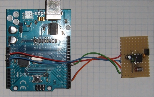
ist ein kleiner Arduino Sketch, mit dem man Pulsbreite oder Frequenz
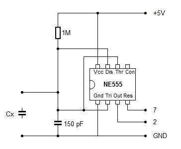
messen kann, umschaltbar. Zusammen mit einem CMOS 555 wird damit
die Kapazität von Kondensatoren gemessen. Der Reset vom 555 wird auf
high geschaltet und dann wird bis zur fallenden Flanke von Int0
gezählt. C=(Pulsbreite -Pulsbreite0) / R und mit R=1 MOhm lässt sich
das einfach berechnen. Die Pulsbreite in us und die Kapazität werden
seriell ausgegeben. Da noch Platz im flash war ist noch ein
Frequenzzähler hinzugekommen. Er hat eine feste gate time von 1 Sekunde
und zeigt die Frequenz in Hz, sogar recht genau, bei 1 MHz nur 7 Hz
zuviel. Es funktioniert bis ca. 5 MHz.
Download: PW_FreqCnt.zip
/*
  Arduino measures Period & Frequency

  connect pin4 to a switch, high measures PW and C, low measures Frequency

  Pulsewidth, pin4 switch to high or open
  with a cmos 555 used to measure capacitance
  connect pin7 to 555 reset(4), Int0 pin2 to 555 out(3)
  C = pulsewidth / R, R = 1 MOhm, astable mode w C0=150pF
  measures pulse width in microseconds on Int0
  Counter1 is counting during Int0 high

  Frequency, pin4 switch to low
  connect pin5 T1 in to signal

  GS 2014

  This is free software; you can redistribute it and/or
  modify it under the terms of the GNU Lesser General Public
  License as published by the Free Software Foundation; either
  version 2.1 of the License, or (at your option) any later version.

  This program is distributed in the hope that it will be useful,
  but WITHOUT ANY WARRANTY; without even the implied warranty of
  MERCHANTABILITY or FITNESS FOR A PARTICULAR PURPOSE.  See the GNU
  Lesser General Public License for more details.

  You should have received a copy of the GNU Lesser General Public
  License along with this library; if not, write to the Free Software
  Foundation, Inc., 51 Franklin St, Fifth Floor, Boston, MA  02110-1301  USA
*/


volatile unsigned long f_freq;
volatile unsigned int f_tics;
volatile unsigned char p_ready;
volatile unsigned char p_mlt;
volatile unsigned long p_pwidth;

unsigned long Frequency;
unsigned long Pulsewidth;
unsigned int PulsewidthZero;
float capacitance;
int cnt;

int pinLed=13;
int pinReset=7;
int pinZero=6;
int pinSwitch=4;

//******************************************************************

void Int0_ISR()
{
    					// wait for Int0 falling
    TCCR1B = TCCR1B & ~7;   		//  then Counter T1 is stopped
    digitalWrite(pinReset, LOW);	 // stop 555 now
    p_ready=1;            		 // set flag for end count Pulsewidth

    p_pwidth=0x10000 * p_mlt;  		// mult T1 #overflows by 65636
    p_pwidth += TCNT1;      		// add counter1 value
    p_mlt=0;
    TIMSK0 |=(1<<TOIE0);     		// enable Timer0 again, millis and delay
}

ISR(TIMER2_COMPA_vect)
{
					// 1ms gate time = 1000 ms fixed
 if (f_tics >= 1000)              	// end of gate time, measurement ready

  {
    TCCR1B = TCCR1B & ~7;   		// Gate Off  / Counter T1 stopped
    TIMSK2 &= ~(1<<OCIE2A);    		// disable Timer2 Interrupt
    TIMSK0 |=(1<<TOIE0);     		// enable Timer0 again // millis and delay
    p_ready=1;         			//  end of count period
                                        // calculate frequeny value
    f_freq=0x10000 * p_mlt;  		// mult #overflows by 65636
    f_freq += TCNT1;      		// add counter1 value
    p_mlt=0;

  }
    f_tics++;            		// count number of T2 interrupts
}

ISR(TIMER1_OVF_vect)
{
    p_mlt++;              		 // count number of Timer1 overflows
}

void setup()
{
  pinMode(pinReset, OUTPUT);
  digitalWrite(pinReset, LOW);  	// stop 555 now
  pinMode(pinLed, OUTPUT);		// on board led
  pinMode(pinZero, INPUT);		// store zero value
  pinMode(pinZero, INPUT_PULLUP);
  pinMode(pinSwitch, INPUT);		// switch PW or frequency
  pinMode(pinSwitch, INPUT_PULLUP);

  Serial.begin(9600);      		  // prepare for serial out

  Serial.println("Pulse / Frequency Counter");
  attachInterrupt(0,Int0_ISR,FALLING); // Catch high too low transition
  // TIMER1_OVF_vect
}

void pwget_ready()
{
    TIMSK0 &=~(1<<TOIE0);       	// disable Timer0 millis and delay
    					// set timer/counter1 normal mode, counting
    TCCR1A=0;                  		//timer/counter1 control register A
    TCCR1B=0;              		// timer/counter1 control register A
    TIMSK1 |=  (1<<TOIE1) ;     	// overflow ISR(TIMER1_OVF_vect)
    p_ready=0;                  	// reset period ready flag
    p_mlt=0;				// counts number of Timer1 overflows
    GTCCR = (1<<PSRASY);        	// reset prescaler Timer1
    TCNT1=0;                    	// Counter1 = 0
}

void freqget_ready()
{
    TIMSK0 &=~(1<<TOIE0);       	// disable Timer0 millis and delay
    					// set timer/counter1 normal mode, counting
    TCCR1A=0;                  		//timer/counter1 control register A
    TCCR1B=0;              		// timer/counter1 control register A
    TIMSK1 |=  (1<<TOIE1) ;     	// overflow ISR(TIMER1_OVF_vect)
    //TCCR1B |=  (1<<CS12)|(1<<CS11) | (1<<CS10) ;
    // External clock source on T1 pin. Clock on rising edge.

    // timer2 setup / is used for frequency measurement gatetime generation
    TCCR2A=0;
    TCCR2B=0;


    //set timer2 to CTC Mode with OCR2A is top counter value
    TCCR2A &= ~(1<<WGM20) ;
    TCCR2A |=  (1<<WGM21) ;
    TCCR2A &= ~(1<<WGM22) ;
    OCR2A = 124;                	// CTC divider by 125
    // timer 2 presaler set to 128 / timer 2 clock = 16Mhz / 256 = 62500 Hz
    TCCR2B |=  (1<<CS20) ;
    TCCR2B &= ~(1<<CS21) ;
    TCCR2B |=  (1<<CS22) ;
    p_ready=0;                  	// reset ready flag
    p_mlt=0;				// counts number of Timer1 overflows
    f_tics=0;
    GTCCR = (1<<PSRASY);        	// reset prescaler Timer1
    TCNT2=0;                    	// timer2=0

    TIMSK2 |=(1<<OCIE2A);       	// enable Timer2 Interrupt

    TCNT1=0;                   		// Counter1 = 0, start counting now
    TCCR1B |= (1<<CS12) | (1<<CS11) | (1<<CS10);
}


void loop() {

  if (digitalRead(pinSwitch) == HIGH) 		// HIGH = PW, LOW=Frequency
  {
        EIMSK |=(1<<INT0);       	        // enable Int0 Interrupt
	pwget_ready();
	digitalWrite(pinReset, HIGH);  		// start 555
	TCCR1B |= (1<<CS10);        		// start T1 counting now

	while (p_ready == 0)		 	// wait for Int0 falling

	Pulsewidth=(15*Pulsewidth + p_pwidth)/16;	// running average
	if (digitalRead(pinZero) == LOW) 	// read the zero pin
	{
	PulsewidthZero=Pulsewidth;		// store zero Pulsewidth
	}
	capacitance=(Pulsewidth-PulsewidthZero)/16.0; //in pF  C=pw/R  R=1 MOhm
	Pulsewidth=Pulsewidth/16;		// in microseconds

	  Serial.print("  PW= ");
	  Serial.print(Pulsewidth);
	  Serial.print("  C= ");
	  if (capacitance < 1000) {
	     Serial.print(capacitance);
	     Serial.println(" pF");
	  } else {
	     Serial.print(capacitance/1000.0);
	     Serial.println(" nF");
	  }
  } else
  {
        EIMSK &=~(1<<INT0);       	        // disable Int0 Interrupt
  	freqget_ready();
	while (p_ready == 0)		 	// wait for gate time
	Frequency=f_freq;
	Serial.print("  F= ");
	Serial.print(Frequency);
	Serial.println(" Hz");
  }
  delay(50);
  digitalWrite(pinLed,!digitalRead(pinLed));  // blink Led 13 on board

}
Elektronik-Labor
Projekte
AVR


