Franzis Tutorial Kit Electronics    

Elektronik-Labor  Literatur  Projekte  Lernpakete  Elektronik-Grundlagen


Franzis Tutorial Kit Electronics

by Burkhard Kainka


This tutorial kit was compiled to introduce you to the most essential fundamentals of electronics. What use is dry theory without practice? So we included an experimental package that contains the most essential components. You will soon become familiar with it and, in addition to the circuitry here presented, will be able to develop and test your own ideas.

1 Introduction  7

2 Experiments with LEDs 17
2.1 Limited current 17
2.2 Colour change  19
2.3 Blocked current  20
2.4 Everything in parallel 21
2.5 The curves of a LED  22
2.6 All connected in series 25

3 Capacitors 27
3.1 Energy storage  27
3.2 Long and short periods 29
3.3 Change direction  30

4 Basic transistor circuits  33
4.1 More power! 33
4.2 Poled in a different way 36
4.3 Electronic one-way streets 37
4.4 Inverted  39
4.5 Light for one minute 41
4.6 When it dawns  42
4.7 Current gain squared  43


4.8 An uneven pair 46
4.9 The LED learns to see  48
4.10 Constant brightness  49
4.11 Mirrored current 51

5 AF amplifiers  53
5.1 A cracking noise from the speaker 53
5.2 Amplified sounds 55
5.3 Volume rise with two stages  57
5.4 Radio sound 59
5.5 Emitter follows base 62
5.6 In push-pull  63

6 Multivibrators  65
6.1 Flip and flop 65
6.2 Igniting and wiping  66
6.3 Triggered brightness 69
6.4 Fed back 71

7 Indicator circuits and oscillators  73
7.1 Strictly alternating  73
7.2 On and off  74
7.3 The brighter the higher 77

7.4 Voltage controls sound 78
7.6 Sawtooth 80

8 Operational amplifiers 83
8.1 Amplify the tiniest difference  83
8.2 Comparison operation  85
8.3 Gain one 87
8.4 Voltage multiplied by two 87
8.5 Amplified sounds 89
8.6 Triangle and rectangle 91

9 The Timer NE555 95
9.1 Generating tones 95
9.2 Precisely clocked  98
9.3 The threshold is reached 99
9.4 Rapid pulse 100
9.5 Lie detector 102

10 Special applications  105
10.1 Charge-pumping 105
10.2 Short wave sounds 107
10.3 Wave-noise of the sea  108
10.4 Smooth flasher 110


4 Basic transistor circuits

The transistor is the key active, i.e. amplifying electronic component. The tutorial kit contains three NPN transistors BC547 and one PNP transistor BC557. The handling of transistors requires some basic knowledge which you can acquire in the experiments we have prepared for you.

4.1 More power!

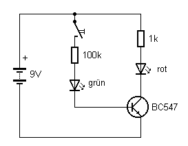
The wiring diagram in fig. 4.1. shows the basic function of a NPN transistor. It is composed of two circuits. The control circuit is passed through by a small base current, the load circuit by a larger collector current. Both currents flow through the emitter. As the emitter lies at the common reference point of the wiring it is also called grounded emitter circuit. When the base circuit is opened, no more load current will flow. The crucial point is that the base current is much smaller than the collector current. The small base current is amplified into a larger collector current. In the actual case the current gain is approximately 100. The 100-kΩ base resistance is one hundred times higher than the series resistor in the load circuit.


Fig. 4.1: NPN transistor in a grounded emitter circuit

In this wiring the transistor functions like a switch. Now there is only a very small voltage difference between the collector and the emitter. The collector current is already limited by the load (resistance and supply voltage) and cannot rise further. This is called “saturation”, i.e., the collector current is “saturated”, (as current is flowing from collector to emitter freely), and the transistor is fully activated.


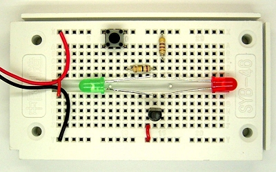
Fig. 4.2: The transistor in a grounded emitter circuit

Build up the experiment following fig. 4.2. The LEDs serve to indicate the currents. The red LED flashes up brightly, the green one is almost imperceptible. Only in a completely darkened room the base current can be perceived as a faint light emitted by the green LED. The difference is an indication of the huge current gain.

In order to determine the maximum current gain of a real transistor you can increase the base resistance. You will still see the red LED flash at 1 mΩ, albeit a little bit dimmer. If you connect two 100-kΩ resistors in series you will have a base resistor with 200 kΩ which can completely activate the transistor. This results in a current gain of approximately 200.
 
In reality, it is not possible to precisely calculate the current gain, despite the high precision technology used in transistor manufacturing. Therefore, you can expect the two transistors BC547B in your tutorial kit to show different current gains if you measure them quite accurately. The transistors undergo tests during manufacture and are classified by their gain factor into the groups A (110 – 220), B (200 – 450) and C (420 – 800). The transistors here are of type B and thus have a minimum gain of 200.

When dimensioning circuits you always have to take into account the uncertainty of the gain factor in order to ensure reliable functioning in a broad range. In the present case the transistor is used like a switch. It will be sufficient to chose the base resistance that will work under worst case conditions, i.e., you better apply a slightly larger base current.

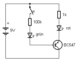
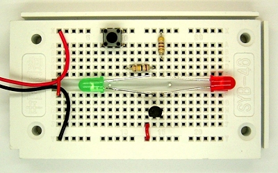
Now interchange the emitter and collector terminals. The transistor will still work, albeit with a considerably smaller collector current. The reason why the transistor will work “in the wrong way” is that it has a symmetrical construction of three layers, N, P, and N. In reality, however, the layers differ, in thickness, so it really matters which N-terminal you connect to the negative pole


Fig. 4.3: The NPN transistor with reversed terminals


Fig. 4.4: Inversion of emitter and collector

In practice, the gain factor for reversed connections ranges between 5 and 20. You will not see more than a faint flashing of the red LED. Now replace the 100-kΩ resistor with a 10-kΩ resistor. The collector current will increase proportionally and the LED will flash more brightly. You can clearly see that the red LED shines brighter than the green one, so it is still being amplified. However, this is not the typical usage of the transistor. In the normal case it would be just an error. So if a circuit performs worse than expected, the connections might have been reversed by accident.


Hinweis für meine deutschsprachigen Leser: Das  Lernpaket Elektronik wurde ursprünglich in der deutschen Fassung entwickelt und nun vom Franzis-Verlag übersetzt.  Wenn Sie Interesse an diesem Thema haben, überlegen Sie, ob es sinnvoll sein könnte die englische Fassung zu nehmen. Sie lernen dann zugleich die Grundlagen der Elektronik und die englische Fachsprache.


Elektronik-Labor  Literatur  Projekte  Lernpakete  Elektronik-Grundlagen