ATtiny10 mit CodeVisionAVRATtiny10 mit CodeVisionAVR
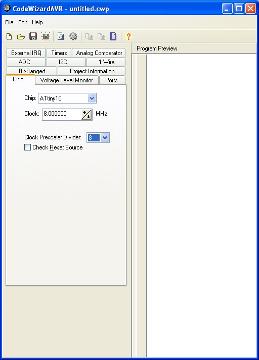
Eine erste Suche im Internet bringt die Info, dass CodeVisionAVR die neuen Chips Tiny4/5/9/10 schon unterstützt. Also die freie Version geladen und gleich gestartet:

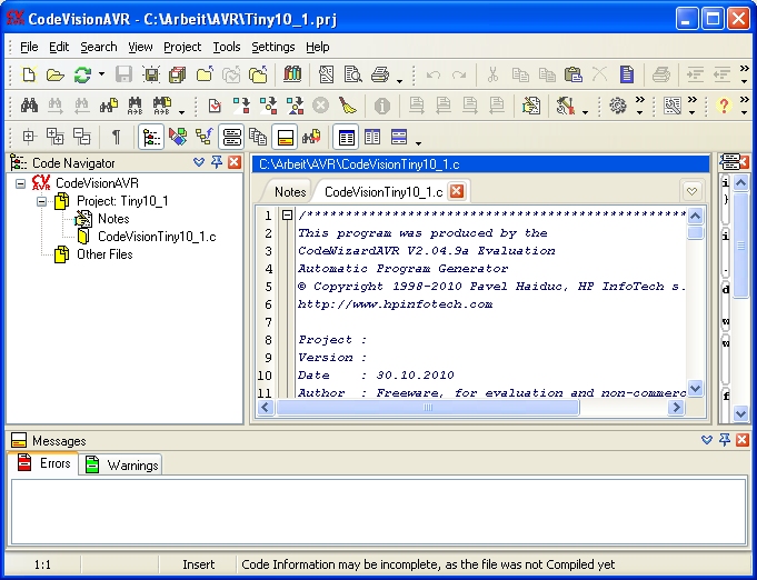
/*****************************************************Der Quelltext enthält alle wichtigen Initalisierungen. Jetzt muss ich nur noch eintragen, was ich eigentlich machen will.
This program was produced by the
CodeWizardAVR V2.04.9a Evaluation
Automatic Program Generator
© Copyright 1998-2010 Pavel Haiduc, HP InfoTech s.r.l.
http://www.hpinfotech.com
Project :
Version :
Date : 30.10.2010
Author : Freeware, for evaluation and non-commercial use only
Company :
Comments:
Chip type : ATtiny10
AVR Core Clock frequency: 1,000000 MHz
Memory model : Tiny
External RAM size : 0
Data Stack size : 8
*****************************************************/
#include <tiny10.h>
// Declare your global variables here
void main(void)
{
// Declare your local variables here
// Main Clock source: Calibrated Internal 8 MHz Osc.
#pragma optsize-
CCP=0xD8;
CLKMSR=0x00;
// Clock Prescaler division factor: 8
CCP=0xD8;
CLKPSR=0x03;
#ifdef _OPTIMIZE_SIZE_
#pragma optsize+
#endif
// Voltage Level Monitor
// Trigger Level: Voltage Level Monitor Disabled
// Interrupt: Off
VLMCSR=0x00;
// Input/Output Ports initialization
// Port B initialization
// Pull-up initialization
PUEB=0x00;
// Func3=In Func2=In Func1=In Func0=In
// State3=T State2=T State1=T State0=T
PORTB=0x00;
DDRB=0x00;
// Break Before Make Mode PORTB: Off
PORTCR=0x00;
// Timer/Counter 0 initialization
// Clock source: System Clock
// Clock value: Timer 0 Stopped
// Mode: Normal top=0xFFFF
// Input Capture on Falling Edge
// Input Capture Noise Canceler: Off
// OC0A output: Disconnected
// OC0B output: Disconnected
TCCR0A=0x00;
TCCR0B=0x00;
TCNT0=0x0000;
ICR0=0x0000;
OCR0A=0x0000;
OCR0B=0x0000;
// External Interrupt(s) initialization
// INT0: Off
// Interrupt on any change on pins PCINT0-3: Off
EICRA=0x00;
EIMSK=0x00;
PCICR=0x00;
// Timer/Counter 0 Interrupt(s) initialization
TIMSK0=0x00;
// Analog Comparator initialization
// Analog Comparator: Off
// Analog Comparator Input Capture by Timer/Counter 0: Off
ACSR=0x80;
while (1)
{
// Place your code here
}
}
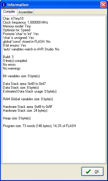
Übersetzen mit Project/Build: Erfolg! Es werden 73 Words (14,3 des Flash) benötigt.
DDRB = 7;

while (1)
      {
      PORTB=7;
      PORTB=0;
      }
}