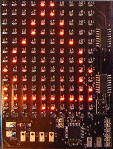
Als erste eigene Anwendung auf dem Pong-Board
entstand dieser Weihnachtsbaum. Es dient vor allem dazu, als kleine
Spielerei das Multiplexen der 120 LEDs auszutesten. Das Multiplexen
erfolgt in der ISR, die bei Zähler 0 Überlauf ausgeführt wird.
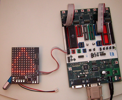
Die
Anoden (10) werden durchgeschaltet, und die Kathoden (12) werden mit
dem Bitmuster, welches in die Schieberegister geschoben wird,
angesteuert. Um eine zweistufige Helligkeit zu erreichen, wird die
Ansteuerung in einen kurzen und einem langen Zyklus unterteilt. Dazu
wird Zähler 0 mit entsprechenden Werten in der ISR geladen.
Das Hauptprogramm initialisiert den „Grafikspeicher" mit den Werten des Umrisses (volle Helligkeit) und führt dann in der Hauptschleife das Tauschen der vertikalen Linien im Inneren mit gedimmter Helligkeit aus. Das erfolgt mit einer bestimmten Geschwindigkeit, und so scheint sich der Baum mal rechts und mal linksrum zu drehen. Entwickelt wurde das Programm mit WinAVR (GCC).
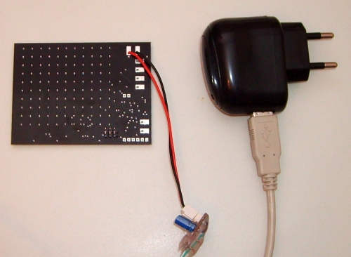
Als Stromversorgung nach dem Flashen dient ein MP3-Player Ladenetzteil, das dem Board über den abgebildeten Adapter 5V zur Verfügung stellt.
Download: C-Quelltext und Hexfile
// using ATMEGA8 on the Conrad Pong PCB
// This code is released to the Public Domain. No warranty for any purpose is given.
// revision (newest first)
// 2009-12-13: finished xmas tree code
// 2009-12-01: initial
// This define is for Visual Studio intellisense, type before any stystem header includes
// It must match the MCU name (MCU = atmega8) in the makefile else intellisense can take you to the wrong definition
#ifndef __GNUC__ // only for the Visual Studio, GCC generates it from MCU name
#define __AVR_ATmega8__
#endif
// Intellisense can be triggered update by ctr+space, or Save all, or at last deleting prj.ncb file and restarting Visual Studio
#include <avr/io.h>
#include <avr/pgmspace.h>
#include <avr/interrupt.h>
#include <avr/wdt.h>
#include <util/delay.h>
#include <stdbool.h>
#include "my_avr_defs.h"
// display orientation landscape if defined, else portrait
//#define LANDSCAPE
#ifdef LANDSCAPE
// width of display (LED count)
#define WIDTH 12
// height of display (LED count)
#define HEIGHT 10
#else
// width of display (LED count)
#define WIDTH 10
// height of display (LED count)
#define HEIGHT 12
#endif
#define CYCLE1_TIME 1 // // cycle 1 is very little of the time of cycle 2, so the brightness is way lower
#define CYCLE2_TIME 32
// cycle 1 is 0.008 millisec
// Time = prescale * counter range / clock frequency
// 0.064 ms = 64 * 1 (CYCLE1_TIME) / 8 000 000 Hz
// cycle 2 is 0.25 millisec
// Time = prescale * counter range / clock frequency
// 2.048 ms = 64 * 32 (CYCLE2_TIME) / 8 000 000 Hz
// global Pixel buffer (always anode, cathode order as this is optimal for the multiplexer)
static byte pixbuf[10][12];
// v is the brightness code, use only 0, 1, and 2, while 2 be the brightest
static inline void SetPixel(byte x, byte y, byte v)
{
#ifdef LANDSCAPE
pixbuf[y][x]= v;
#else
pixbuf[x][y]= v;
#endif
}
static inline byte GetPixel(byte x, byte y)
{
#ifdef LANDSCAPE
return pixbuf[y][x];
#else
return pixbuf[x][y];
#endif
}
// the xmas tree bit pattern
static const uint PROGMEM pics[12] = {
//0123456789
0b0000110000, //0
0b0000110000, //1
0b0001001000, //2
0b0001001000, //3
0b0010000100, //4
0b0100000010, //5
0b0100000010, //6
0b1000000001, //7
0b0100000010, //8
0b1000000001, //9
0b1111111111, //10
0b0000110000, //11
};
// where the y lines with inside tree area lie
#define INSIDE_BEGIN 2
#define INSIDE_END 10
// init all stuff of the AVR for safe operation
static void AVR_Init(void)
{
//cli(); // interrupts are disabled at startup
// watchdog should reset after 15 millisec (protect the LEDs, although the max current is OK for always on)
wdt_enable(WDTO_15MS);
// activate internal pullups to avoid floating input pins
PORTB= (1u<<6)|(1u<<7);
PORTC= (1u<<4)|(1u<<5)|(1u<<6)|(1u<<7);
PORTD= (1u<<0)|(1u<<1)|(1u<<2)|(1u<<3);
// set output ports
DDRB= (1u<<0)|(1u<<1)|(1u<<2)|(1u<<3)|(1u<<4);
DDRC= (1u<<0)|(1u<<1)|(1u<<2)|(1u<<3);
DDRD= (1u<<4)|(1u<<5)|(1u<<6)|(1u<<7);
// 8bit timer0 init, internal clock / 64
// LED multiplexing occurs on overflow0 Intr
TCCR0= (1u<<CS01)|(1u<<CS00);
TIMSK= (1u<<TOIE0); // interrupt on overflow
}
int __attribute__ ((OS_main)) main(void)
{
// make the outline pic from the xmas tree
for (byte y= 0; y < HEIGHT; ++y) {
uint row= pgm_read_word(&pics[y]);
uint shft= 1;
for (byte x= 0; x < WIDTH; ++x) {
if (shft & row)
SetPixel(x,y,2); // full brightness
shft*= 2;
}
}
for (byte x= 0; x < WIDTH; ++x)
SetPixel(x,10,2); // the only full line is set manually as above algorithm screws on that
AVR_Init();
sei(); // we want interrupts globally now
bool even= false;
for (;;) {
// slowly swap the interiour lines
for (byte y= INSIDE_BEGIN; y < INSIDE_END; ++y) {
uint row= pgm_read_word(&pics[y]);
uint shft= 1;
bool inside= false;
for (byte x= 0; x < WIDTH; ++x) {
if (shft & row) {
if (!inside)
inside= true;
else
break;
}
else if (inside)
SetPixel(x,y, x % 2 == even ? 0 : 1); // low brightness for interiour (odd columns)
shft*= 2;
}
}
even = !even;
_delay_ms(160);
}
/* simple kind of snake for test
for (byte y= 0; y < HEIGHT; ++y) {
for (byte x= 0; x < WIDTH; ++x) {
wdt_reset(); // keep watchdog watching...
SetPixel(x,y,1);
_delay_ms(45);
}
}
for (byte y= 0; y < HEIGHT; ++y) {
for (byte x= 0; x < WIDTH; ++x) {
wdt_reset(); // keep watchdog watching...
SetPixel(x,y,2);
_delay_ms(45);
}
}
for (byte y= 0; y < HEIGHT; ++y) {
for (byte x= 0; x < WIDTH; ++x) {
wdt_reset(); // keep watchdog watching...
SetPixel(x,y,3);
_delay_ms(45);
}
}
for (byte y= 0; y < HEIGHT; ++y) {
for (byte x= 0; x < WIDTH; ++x) {
wdt_reset(); // keep watchdog watching...
SetPixel(x,y,0);
_delay_ms(45);
}
}
*/
}
// interrupt routine
// will put the pixel data to the LED matrix
// select actual cathode line by the shift register, then put the anodes with the ports to high for the on pixel
//
// Note:
// Because CLK connected to MOSI, not SCK, we cannot bitbang with SPI
SIGNAL (SIG_OVERFLOW0)
{
static bool firstcy;
static byte anode;
static byte shift= 1;
firstcy = !firstcy;
if (firstcy) {
TCNT0= 256-CYCLE1_TIME;
anode++;
shift*=2;
if (anode == 8)
shift= 1;
else if (anode == 10) {
anode= 0;
shift= 1;
}
}
else
TCNT0= 256-CYCLE2_TIME;
byte cmp= firstcy ? 1 : 2;
// bitbang the cathode pattern through the shift register
for (byte b= 0; b < 12; ++b) {
if (pixbuf[anode][b] == cmp)
PORTB &= ~(1u<<4); // first cathode line put to low, this low is bitbanged through the registers
else
PORTB |= (1u<<4); /// next ones put to high
// impulses for the shift registers (CLK)
PORTB |= (1u<<3);
PORTB &= ~(1u<<3);
}
wdt_reset(); // keep watchdog watching...
// reset all anode lines
PORTB &= ~((1u<<0)|(1u<<1));
PORTC &= ~((1u<<0)|(1u<<1)|(1u<<2)|(1u<<3));
PORTD &= ~((1u<<4)|(1u<<5)|(1u<<6)|(1u<<7));
// impulses for the shift registers (strobe)
PORTB |= (1u<<2);
PORTB &= ~(1u<<2);
// set according anode line
if (anode < 4)
PORTC |= shift;
else if (anode < 8)
PORTD |= shift;
else
PORTB |= shift;
}