Car Voltmeter with ATtiny15
This is not a real voltmeter but more an indicator for the battery voltage with 3 leds.
I'm using it in my car and with a quick glance I can see it's all green and the battery is ok, easier than to read a display in heavy traffic. It could be done differently by why not give some task to the old workhorse ATtiny15.
It is reading the battery voltage with ADC3 and a voltage divider, R5 is 24.8k (sorry) and R4 is 10k to GND. Then there are some thresholds defined in the assembler program and a red, green, and yellow led is turned on depending on the voltage: red below 10 V, red&green 11.5V, green between 12 and 13.8V and yellow above 14V. Nice and easy. With another voltage divider just redefine the thresholds. There is a reverse diode at the input to protect against spikes in a car. It might be wise to add a 10 Ohm resistor in front, but it works like this in my car and has not blown a fuse yet.
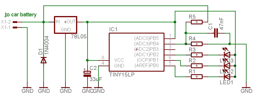
The circuit diagram of the so-called car voltmeter, PB0 and R1 (470Ohm) go to the red LED1, LED2 is green and LED3 is yellow
It might be build even smaller than you see here and could fit in the plug of the cigarette lighter. I drilled holes in the dashboard, it's an old car.
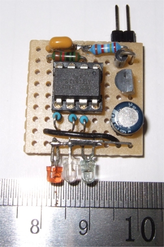
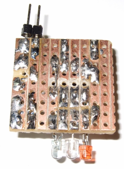
A possible layout of the board, top and bottom view.
It is a quick and easy project but once you have it you'll find it useful.
download 3led12V2.asm
This program is distributed in the hope that it will be useful but WITHOUT
ANY WARRANTY;
References
Atmel datasheet ATtiny15, Atmel.com
Gerd's AVR assembler version 2.7: http://www.avr-asm-tutorial.net/gavrasm/index_en.html
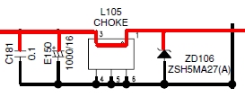
Nachtrag: Sebastian Heyn wies darauf hin, dass die Schaltung nicht gegen Spannungsspitzen geschützt ist, wie es im Automotive-Bereich üblich ist. Man kann z.B. eine Suppressordiode mit einem Vorwiderstand einsetzen. Üblich ist auch eine Induktivität in der Versorgungsleitung. Bei privaten Spielereien kann man die Schaltspannung vom Radio (für externe Verstärker oder Phantomspeisung) nehmen, die ist fast immer durch die Schutzmechanismen des Radios mitgeschützt.
;***************************************************************************
; AT15  3 Leds on PB 0 1 2, red green yellow, use threshold
;	simple car Voltmeter, 12 V, indicate battery voltage
;	The timing is adapted for 1.6 MHz
;  	OSCCAL config val=0x74 (not critical)
; 	ATtiny15 GS 2009
;
;***************************************************************************
;
;  This program is free software; you can redistribute it and/or
;  modify it under the terms of the GNU General Public License.
;  This program is distributed in the hope that it will be useful,
;  but WITHOUT ANY WARRANTY;
;***************************************************************************
;			ATtiny15 dip
;	(RESET/ADC0) 	PB5	VCC
;	(ADC3) 		PB4	PB2 (ADC1/SCK/T0/INT0)
;	(ADC2) 		PB3	PB1 (AIN1/MISO/OC1A)
;			GND	PB0 (AIN0/AREF/MOSI)
;
;***************************************************************************
; voltage divider 10 k & 24.8 k on ADC3, 24,8k => 100k parallel 33k
;***************************************************************************

.DEVICE ATtiny15	;for gavrasm

.equ	avgcnt		= 16
				;Led	Voltin

.equ 	Volt1		= 176  	;red	10
.equ 	Volt2		= 191   ;redgn	11.5
.equ 	Volt3		= 197   ;gn	12
.equ 	Volt4		= 217   ;gn	13.8
.equ 	Volt5		= 220   ;yel	14

.equ	toggle		= PB3

;***************************************************************************
.def	zero		= r14
.def	S		= r15
.def	temp		= r16
.def 	count		= r17
.def 	lcnt		= r18
.def	next_step	= r19
.def	av_l		= r20	; Average Low Byte (ADC Measurement)
.def	av_h		= r21	; Average High Byte (ADC Measurement)
.def	ledflag		= R22	; set Leds

.cseg
.org 0
; Reset-vector to adress 0000
	rjmp	reset
	reti 			; INT0addr= 0x0001 External Interrupt 0
	reti 			; PCI0addr= 0x0002 Pin Change Interrupt
	reti 			; OC1addr = 0x0003 Timer/Counter1 Compare Match
	reti 			; OVF1addr= 0x0004 Timer/Counter1 Overflow
	rjmp	TIM0_OVF	; OVF0addr= 0x0005 Timer/Counter0 Overflow
	reti 			; ERDYaddr= 0x0006 EEPROM Ready
	reti 			; ACIaddr = 0x0007 Analog Comparator
	reti 			; ADCCaddr= 0x0008 ADC Conversion Ready

;***************************************************************************
;* "TIM0_OVF" - Timer/counter overflow interrupt handler
;*
;* The overflow interrupt toggles  every 1.28ms
;*
;***************************************************************************
TIM0_OVF:	in	S,sreg			; Updated every 1.28 ms, calibrate OSCCAL

		sbis	PINB,  toggle		; skip if set
		sbi	PORTB, toggle		; set output PORTB
		sbic	PINB,  toggle	 	; skip if set
		cbi	PORTB, toggle

		inc	count
		inc	next_step
		out	sreg,S
		reti
;***************************************************************************
reset:

		; writing the calibration byte to the OSCCAL Register.
;		ldi	temp,0x74    	; test
;		out	OSCCAL,temp 	; for the clock
;		nop
;		nop
; Port B
		ldi	temp,0b00001111	 	; set hi
		out	PORTB,	temp		; 1 = pull-up , 0 = float
		ldi	temp,0b00001111		; low 4 bits are 1 = output
		out	DDRB,	temp       	; to data direction register

;***************************************************************************
; AD-Converter setup:
						; ADMUX: REFS1 REFS0 ADLAR – – MUX2 MUX1 MUX0
						; If ADLAR is set, the result is left-adjusted.
		ldi 	temp, 0b00100011 	; Ch 3 input=PB4, REFS0,1 =00 Vcc is RefVoltage
		out 	ADMUX, temp
						; ADCSR: ADEN ADSC ADFR ADIF ADIE ADPS2 ADPS1 ADPS0
		ldi	temp, 0b11010011 	; ADC init single conversion prescaler 8:
		out 	ADCSR, temp

;***************************************************************************
; timer setup:
		ldi	temp,0b00000010		; Timer/Counter 0 clocked at CK/8 = 5 us
		out	TCCR0,temp		; 1,6 Mhz
		;Bit 1 – TOIE0: Timer/Counter0 Overflow Interrupt Enable
		ldi	temp,0b00000010 	; $02  set Bit 1
		out	TIMSK,temp 		; in the Timer Interupt Mask Register
		out	TCNT0,zero		; Timer/Counter 0 clear

		sbi	AcsR,Acd		; Disable Comparator

		clr	av_l
		clr	av_h			; Clear Average Registers
		clr	next_step
		sei				; Enable gobal interrupt

;***************************************************************************

		out	PORTB,zero		; test leds, all on
		clr	next_step
test:		cpi	next_step, 250		; short test
		brne	test


		clr	next_step
main:		cpi	next_step, 8		; update time
		brne	main
		clr	next_step

		rcall	convert_average		; Measure Volt 0..255
		ser 	ledflag			; all 1 = leds off

		cpi	av_l, Volt1		; threshold 10 V
		brsh	m2			; next
		cbr	ledflag, 1		; is below 10 V, turn led on
		rjmp	mx
m2:		cpi	av_l, Volt2		; threshold 11.5
		brsh	m3			; next
		cbr	ledflag, 1
		rjmp	mx
m3:		cpi	av_l, Volt3		; threshold 12
		brsh	m4			; next
		cbr	ledflag, 3
		rjmp	mx
m4:		cpi	av_l, Volt4		; threshold 13.8
		brsh	m5			; next
		cbr	ledflag, 2
		rjmp	mx
m5:		cpi	av_l, Volt5		; threshold 14
		brsh	m6			; next
		cbr	ledflag, 6
		rjmp	mx
m6:
		cbr	ledflag, 4
mx:

		out	PORTB,ledflag		;

		rjmp	main

;***************************************************************************
; ADC Average
; function measures the voltage Vin and returns the
; average value in av_l 0..255, avgcnt=16
;***************************************************************************
convert_average:
		ldi	temp,0b00100011
		out	ADMUX, temp		; Set ADC Channel
		clr	av_l
		clr	av_h			; Clear Average Registers
		ldi	lcnt,avgcnt 		; Set loop counter
convert_start:
		ldi	temp,0b11010011 	;

		out	ADCSR,temp		; Start A/D Conversions
convert_wait:
		sbis	ADCSR, ADIF
		rjmp	convert_wait		; Wait for Conversion to finish
		in	temp, ADCH
		add	av_l, temp
		adc	av_h, zero		; Add measured value to average
		dec	lcnt
		brne	convert_start		; Repeat lcnt times

		ldi	lcnt,avgcnt/4		; Set shift counter
convert_avg:
		lsr	av_h
		ror	av_l			; av_h:av_l = av_h:av_l/2
		dec	lcnt
		brne	convert_avg		; Repeat (avg_loop_cnt) times
		;cbi	ADCSR,ADEN
		ret				; return to measure