
Charlieplex Clock with ATtiny2313
When the old clockwork died the whole thing looked too nice to throw away. Why not put some leds inside and recycle.
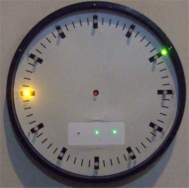
The clock, now it is 9 hours and 10 minutes and the binary panel shows 3 minutes more, the time is 9:13. Easy to read for us electronic freaks.
The inner orange leds show the hours, the outer green leds show 5 minutes and the panel below shows minutes 0-4 in binary.
Now the challenge was to use one ATtiny 2313 to turn on the 12 hour leds, the 12 minute leds and 3 more on the binary panel. Charlieplexing was the answer, with N pins we can control N*(N-1) leds. Four pins control 12 leds. This technique was proposed in early 1995 by Charlie Allen at Maxim Integrated Products.
On PORTB the lower 4 pins are assigned to the 12 hour orange leds and the upper 4 pins turn on the green 5 minute leds. The binary panel is conventional 1 pin per led. As a clock it is using a 4 MHz quartz, a small pushbutton is there to advance the time every full hour and a RS232 interface to set the time. It won't send to the PC, receive only to set the time like h21 for the hours or m15 to set the minutes.
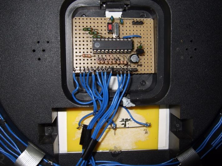
Backside of the clock, a lot of wiring as you can see.
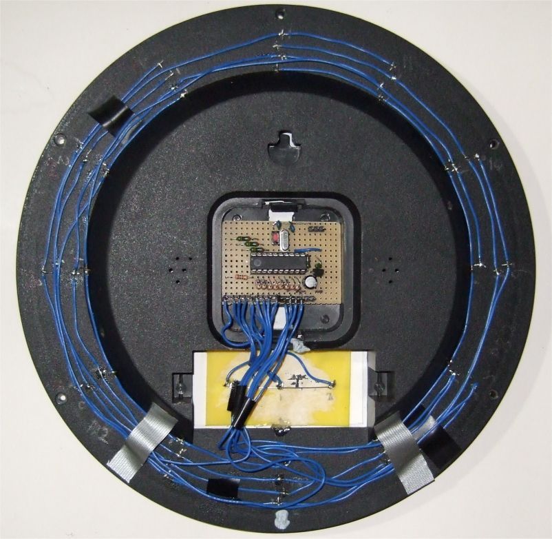
Connecting the leds needs a high level of concentration on a quiet day, there is no margin for error. Troubleshooting in charlieplexed led circuits is not easy.
It starts to drill small holes for all the leds and push them in, then bend the wires to keep them in place. Wiring is the next task.
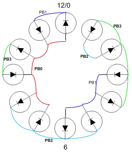
Above ugly diagram shows the Charlieplexed Leds on PB 0 1 2 3, which are the inner leds. On PB 4 5 6 7 are the outer 12 leds, the same wiring again, PB4 like PB0...
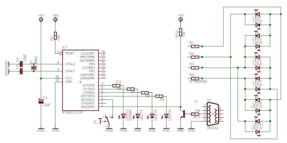
The cicuit diagram, the 12 orange leds are connected to PB0123 and the12 green leds to PB4567. Resistors could be 100 Ohm.
The small binary panel leds are connected to PD5 4 3, the led in the middle of the clock to PIND6, it turns on between 18h and 6h. This led is using a 24 h clock, the other leds are on a 12 hour clock timing. The outer green leds flash once every second to show the clock is working.
This was the difficult part, now comes the easy part, the assembly of the contoller board.
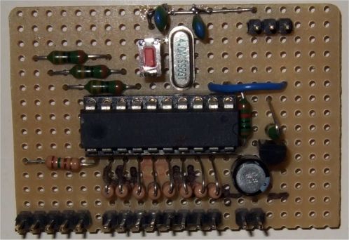
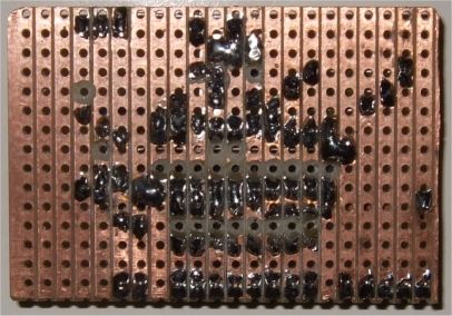
Top and bottom view of the controller board. Not many parts needed, the ATtiny2313, a quartz and some resistors.
The assembler program uses a table to charlieplex the leds, e.g. .db 0b00110001 where the upper 4 bits are going to DDRB and the lower 4 bits set PORTB. The time is controlled by a Timer1 Compare Match A interrupt which fires every 10 ms, all timing is derived frome here. The External Interrupt0 on PIND2, when S1 pushbutton is pressed, will advance the hour to allow a manual time setting every full hour, otherwise use the RS232 interface anytime. When the power is turned on the clock will do a test of the leds and then starts to show the time. Enjoy.
The wiring is a bit complex but finally you'll have a very unique clock.
download Cplxclk6.asm
This program is distributed in the hope that it will be useful but WITHOUT
ANY WARRANTY;
References
Atmel datasheet ATtiny2313, Atmel.com
see Wikipedia on Charlieplexing and maxim-ic.com: http://pdfserv.maxim-ic.com/en/an/AN1880.pdf
Gerd's AVR assembler version 2.7: http://www.avr-asm-tutorial.net/gavrasm/index_en.html
;***************************************************************************
; ATiny2313 clock with 12 leds inner and 12 leds outer ring
; 	ATiny2313 GS 10-2011
;	Charlieplex 12 Leds + 12 Leds on PORTB, use Led table
;	12 hour clock for leds, 24 for NightOn
;	PORTB 0 1 2 3 outer leds 12 green,  minutes
;	PORTB 4 5 6 7 inner leds 12 orange, hours
;	PORTD 3 4 5   small panel leds, 0..4 minutes binary
;	The timing is adapted for 4 MHz
;
;;***************************************************************************
;                 ATiny2313  PDIP
;
; (RESET/dW) 	  PA2 1   20 VCC
; (RXD) 	  PD0 2   19 PB7 (UCSK/SCK/PCINT7)
; (TXD) 	  PD1 3   18 PB6 (MISO/DO/PCINT6)
; (XTAL2) 	  PA1 4   17 PB5 (MOSI/DI/SDA/PCINT5)
; (XTAL1) 	  PA0 5   16 PB4 (OC1B/PCINT4)
; (CKOUT/XCK/INT0)PD2 6   15 PB3 (OC1A/PCINT3)
; (INT1) 	  PD3 7   14 PB2 (OC0A/PCINT2)
; (T0) 		  PD4 8   13 PB1 (AIN1/PCINT1)
; (OC0B/T1) 	  PD5 9   12 PB0 (AIN0/PCINT0)
;		  GND 10  11 PD6 (ICP)
;***************************************************************************

.DEVICE ATtiny2313	;for gavrasm

.equ 	clock 		= 4000000
.equ 	baudrate 	= 9600
.equ 	baudval 	= clock/(16*baudrate)-1
; more Definitions

.equ	c_value		= 40000-1	;Compare value for output compare interrupt

.equ	Nighton		= PIND6			; PIND6 out Nighton 18h-6h
.equ	Led0		= PIND5			; small panel Leds
.equ	Led1		= PIND4			;
.equ	Led2		= PIND3			;
.equ	Poweron		= PIND1			; use txd

; use r0, r1 to set leds
.def	zero		= r14
.def	sr		= r15

.def	temp		= r16
.def 	count		= r17
.def 	Mincnt		= r18
.def	next_step	= r19
.def	LedcntMin 	= r20
.def	LedcntHrs 	= r21
.def	second  	= r23
.def	minute		= r24
.def	hour		= r25
.def	LedPD0		= r26
.def	LedPD1		= r27
.def	ScratchH	= r26		; use in bcd2bin
.def	ScratchL	= r27		; use in bcd2bin
.def	cnt24h		= r28
.def	test2		= r29


.cseg
.org 0
	rjmp	RESET
	rjmp	ExtInt0		; INT0 set hour
	reti			; INT1
	reti
	rjmp	T1OC1A		; Initialize T1 Compare Match A interrupt vector
.org 7
	rjmp	RX_COMPLETE_INT

;**********************************************************************
; Timer1 Compare Match A interrupt **********************
; 		10 ms
;**********************************************************************


T1OC1A:		in	sr,sreg

		inc	count			; count up
		cpi 	count, 100		; 100 * 10 ms = 1 s
		brlo	OC1Ab
		clr	count

		inc	next_step
		inc	second
		cpi	second,60
		brne	OC1Ab
		clr	second

		inc	minute

		inc	Mincnt
		cpi	Mincnt,5			; 12 leds, 60min/12
		brne	OC1min
		clr	Mincnt
		inc	LedcntMin
OC1min:
		cpi	minute,60
		brne	OC1Ab
		clr	minute
		clr	LedcntMin
		clr	Mincnt

		inc 	hour
		inc	cnt24h			; 24 h
		inc	LedcntHrs
		cpi	hour,12			; leds 12 h clock
		brne	OC1hr1
		clr	hour
		clr	LedcntHrs
OC1hr1:
		cpi	cnt24h,24		; 24 h
		brne	OC1Ab
		clr 	cnt24h

OC1Ab:
		out	SREG,sr
		reti


;**********************************************************************
; External Interrupt0 on PIND2, button pressed
;  (Inc hour)
;**********************************************************************
ExtInt0:
		in	sr, SREG
		clr	count
EI0_1:		dec	count			; debounce
		brne	EI0_1
		sbic 	PIND, PIND2   		; check if button is still low
		rjmp	EI0_x

		clr	Mincnt
		clr	LedcntMin
		clr	count
		clr	second			; counters
		clr	minute
		inc	hour
		inc	LedcntHrs
		inc 	cnt24h
		cpi	hour,12			; 12 h leds
		brne	EI0_2
		clr	hour
		clr	LedcntHrs
EI0_2:		cpi	cnt24h,24		; 24 h
		brne	EI0_x
		clr 	cnt24h
EI0_x:		out	SREG, sr
		reti

;**********************************************************************
;*
;* "BCD2bin8" - BCD to 8-bit binary conversion
BCD2bin8:
BCDb8_0:	subi	ScratchH,1	; fBCDH = fBCDH - 1
		brcs	BCDb8_1		; if carry not set
		subi	ScratchL,-10	;    result = result + 10
		rjmp	BCDb8_0		;    loop again
BCDb8_1:
		ret			;else return

;**********************************************************************
; Interrupt routine for incoming bytes on the RS232 link
;**********************************************************************

RX_COMPLETE_INT:
		in	sr, SREG
		push	temp
		in 	temp,UDR
		cpi		temp,'h'		; hour => h21
		brne	rx_2
	        rcall 	SerIn           ; read hr hi
	        subi 	temp, 48	; make BCD
	        mov 	ScratchH, temp
	        rcall  	SerIn           ; read hr lo
	        subi 	temp, 48	; make BCD
	        mov 	ScratchL, temp
	        rcall	BCD2bin8
	        mov	cnt24h, ScratchL
	        mov	hour, ScratchL
	        mov	LedcntHrs, ScratchL
	        cpi	hour, 12
	        brlo	rx_exit
	        subi	hour, 12
	        mov	LedcntHrs, hour
		rjmp	rx_exit
rx_2:
		cpi		temp,'m'		; minute
		brne	rx_3
	        rcall 	SerIn           ; read hr hi
	        subi 	temp, 48	; make BCD
	        mov 	ScratchH, temp
	        rcall  	SerIn           ; read hr lo
	        subi 	temp, 48	; make BCD
	        mov 	ScratchL, temp
	        rcall	BCD2bin8
	        mov	minute, ScratchL
	        mov	LedcntMin, ScratchL
		clr	Mincnt
		rjmp	rx_exit
rx_3:
		cpi		temp,'s'		; main timer speed => s+binary
		brne	rx_4
		rcall	SerIn
		out	OCR1AH,temp
		rcall	SerIn
		out	OCR1AL,temp
		rjmp	rx_exit
rx_4:
		cpi		temp,'1'		; hour
		brne	rx_5
	        rcall  	SerIn           		; read
	        mov	hour, temp
	        mov	LedcntHrs, temp
	        mov	cnt24h, temp
		rjmp	rx_exit
rx_5:
		cpi		temp,'2'		; min
		brne	rx_6
	        rcall  	SerIn           		; read
	        mov	minute, temp
	        mov	LedcntMin, temp
		rjmp	rx_exit
rx_6:
		cpi		temp,'D'		;
		brne	rx_7
		rjmp	rx_exit
rx_7:
		cpi		temp,'?'		; send
		brne	rx_15
		ldi	temp,'H'			; reply with H hms
		rcall	send_char
		mov	temp,hour
		rcall	send_char
		mov	temp,minute
		rcall	send_char
		mov	temp,second
		rcall	send_char
		rjmp	rx_exit

; unknown command, just ignore it
rx_15:

rx_exit:
		pop	temp
		out	SREG, sr
		reti

;**********************************************
;* SerIn  Returns serial port input in temp  *
;**********************************************
SerIn:
        sbis    USR,RXC        ;wait for a character
        rjmp    SerIn
        in      temp,UDR       ;read value
        ret

;
; send char in temp
;

send_char:
	 	sbis 	UCSRA, UDRE		; wait for UDR
		rjmp	send_char		; no, wait some more
		out	UDR,temp		; send char
		ret				; and return

;********************************************************************
reset:		ldi  	temp,low(RAMEND)	;Initialize stackpointer
		out	SPL,temp

;************** Ports *****************************************************
		; Port B
		ldi	temp,0b00000000 	; LED ports are output, 1 = output , 0 = input
		out	DDRB,temp       	; to data direction register
		ldi	temp,0b00000000 	; set pullup and pins 0,1 hi
		out	PORTB,	temp		; 1 = pull-up , 0 = float

		; Port D
		ldi	temp,0b01111000 	; output  PD6543
		out	DDRD,temp       	; to data direction register D
		ldi	temp,0b00000101 	; set pullup
		out	PORTD,	temp		; 1 = pull-up , 0 = float

;************** RS 232  ***************************************************
		ldi	temp,low(baudval)	; UBRRL set uart speed
		out	UBRRL,temp
		ldi	temp,high(baudval)	; UBRRH set uart speed
		out	UBRRH,temp
						; 98 = 10011000
		ldi	temp,0x90		; UCSRB=UCR enable RXint and enable rx only
		out	UCSRB,temp		; UCSRB: RXCIE TXCIE UDRIE RXEN TXEN UCSZ2 RXB8 TXB8

;************** INT 0/1 ***************************************************
		ldi	temp, 0b00000000	;Disable INT before changing MCUCR
		out	GIMSK, temp
		ldi	temp, 0b00001010	;Enable
		out	MCUCR, temp		;falling edge

		;ldi	temp, 0b11000000	;Enable INT0 and INT1
		ldi	temp, 0b01000000	;Enable INT0 (buttons)
		out	GIMSK, temp

;************** Timer1 ***************************************************

		ldi 	temp,high(c_value)	;Load compare high value
		out	OCR1AH,temp
		ldi 	temp,low(c_value)	;Load compare low value
		out	OCR1AL,temp
		ldi 	temp,0x00
		out 	TCNT1H,temp		;Clear timer high byte
		out 	TCNT1L,temp		;Clear timer low byte
		out 	TCCR1A,temp		;TOIE1 OCIE1A OCIE1B – ICIE1 OCIE0B TOIE0 OCIE0A: TIMSK
		ldi 	temp,(1<<OCIE1A)	;+(1<<OCIE0B)
		out	TIFR,temp		;Clear pending timer interrupt
		out	TIMSK,temp		;Enable Timer compare interrupt
		ldi 	temp,0b00001001		;0x9, start
		out 	TCCR1B,temp		;Clear timer on compare match,CK/1

;*************** misc *****************************************************
		ldi	TEMP,(1<<ACD)		; turn off the analog comparator
		out	ACSR,TEMP		; to minimize current draw

		clr	count
		clr	second			; counters
		clr	minute
		clr	hour
		clr	LedcntMin
		clr	LedcntHrs

		sei				; Enable gobal iterrupt

;****************main************************************************

		sbi 	PORTD, Nighton		; test Nighton led
		clr	next_step
testnight:	cpi	next_step, 1		; 1 sec time
		brlo	testnight
		cbi 	PORTD, Nighton

		clr	cnt24h			; test all leds
		clr	Mincnt
		ldi	ZH,high(2*Led12)	; setup Z pointer hi
testleds:	ldi	ZL,low(2*Led12)		; Leds upper 4 bit DDRB lower 4 bit PORTB

		add	ZL, cnt24h		; table offset
		lpm	r0, Z
		lpm	r1, Z
		tst	r0			; 0 is end of table
		breq	m1

		rcall 	Ledset			; set PORTB and DDRB
		inc 	cnt24h
		rcall	LedSetPanel		; small panel Leds
		inc	Mincnt
		cpi	Mincnt,5		; 12 leds, 60min/12
		brne	test1
		clr	Mincnt

test1:		clr	next_step
testwait:	cpi	next_step, 1		; wait time
		brlo	testwait
		rjmp	testleds


;***************************************************************************
m1:
		clr	count			; start at 00:00:00
		clr	second			; counters
		clr	minute
		clr 	cnt24h
		clr	hour
		clr	LedcntMin
		clr	LedcntHrs
		clr	Mincnt

mclr:		clr	next_step
main:
;		sbic	PINB, Poweron		; check if power low
;		rjmp	mdisp			; else show
;		out	DDRB, zero		; switch off driver
;		cbi	PORTB, Nighton
;		cbi	PORTD, Led0
;		cbi	PORTD, Led1
;		cbi	PORTD, Led2
;		rjmp	mclr

mdisp:		cpi	next_step, 1		; reaction time
		brlo	main


		ldi	ZH,high(2*Led12)	; setup Z pointer hi to Leds
		ldi	ZL,low(2*Led12)		; Leds upper 4 bit DDRB lower 4 bit PORTB
mflash:
		lpm	r0, Z			; flash leds
		tst	r0			; 0 is end of table
		breq	mset
		rcall 	Ledset			; set PORTB and DDRB
		clr	test2			; small delay
mdly:		dec	test2
		brne	mdly
		inc	ZL
		rjmp	mflash

mset:
		ldi	ZH,high(2*Led12)	; setup Z pointer hi to Leds
		ldi	ZL,low(2*Led12)		; Leds upper 4 bit DDRB lower 4 bit PORTB
		add	ZL, LedcntMin		; table offset min led
		lpm	r0, Z

		ldi	ZL,low(2*Led12)		; Leds upper 4 bit DDRB lower 4 bit PORTB
		add	ZL, LedcntHrs		; table offset hour led
		lpm	r1, Z

		rcall 	Ledset			; set PORTB and DDRB
		rcall	LedSetPanel		; small panel Leds

		cpi	cnt24h, 18		; Nighton test
		brne	m_off
		sbi	PORTD, Nighton
m_off:
		cpi	cnt24h, 6
		brne	mcont
		cbi	PORTD, Nighton

mcont:		clr	next_step
		rjmp	main

;***************************************************************************

LedSetPanel:
		cpi	Mincnt, 0
		brne	LSP1
		cbi	PORTD, Led0
		cbi	PORTD, Led1
		cbi	PORTD, Led2
		rjmp	LSPex
LSP1:
		cpi	Mincnt, 1
		brne	LSP2
		sbi	PORTD, Led0
		cbi	PORTD, Led1
		cbi	PORTD, Led2
		rjmp	LSPex
LSP2:
		cpi	Mincnt, 2
		brne	LSP3
		cbi	PORTD, Led0
		sbi	PORTD, Led1
		cbi	PORTD, Led2
		rjmp	LSPex
LSP3:
		cpi	Mincnt, 3
		brne	LSP4
		sbi	PORTD, Led0
		sbi	PORTD, Led1
		cbi	PORTD, Led2
		rjmp	LSPex
LSP4:
		cpi	Mincnt, 4
		brne	LSPex
		cbi	PORTD, Led0
		cbi	PORTD, Led1
		sbi	PORTD, Led2
LSPex:		ret


;***************************************************************************

Ledset:		mov	LedPD0, r0		; subroutine to set Leds, input r0
		andi	LedPD0, 0x0F		; lower 4 bit PORTB, inner led
		mov	LedPD1, r1		; input r1
		andi	LedPD1, 0x0F		; upper 4 bit PORTB, outer leds
		swap	LedPD1
		or	LedPD1,LedPD0
		out	PORTB, LedPD1

		mov	LedPD0, r0
		swap 	LedPD0			; swap
		andi	LedPD0, 0x0F		; upper 4 bit DDRB, lower 4 bit DDRB, inner led
		mov	LedPD1, r1		; input r1
		andi	LedPD1, 0xF0		; upper 4 bit DDRB, outer leds
		or	LedPD1,LedPD0

		out	DDRB, LedPD1	       	; to data direction register
		ret

; force table to begin at 256 byte boundary

.org 0x200


; Charlieplex Leds on PB 0 1 2 3, PORTB 4 5 6 7 outer leds
; upper 4 bit DDRB lower 4 bit PORTB

Led12: ;led0..11 Cplex 0=12 hrs


.db 	0b00110001, 0b11001000 ; 12=0, 1
.db 	0b11000100, 0b10101000 ;2 3
.db 	0b10100010, 0b01100100 ;4 5
.db 	0b01100010, 0b01010100 ;6 7
.db 	0b01010001, 0b10011000 ;8 9
.db 	0b10010001, 0b00110010 ;10 11
.db	0,0