
Multi-DVM
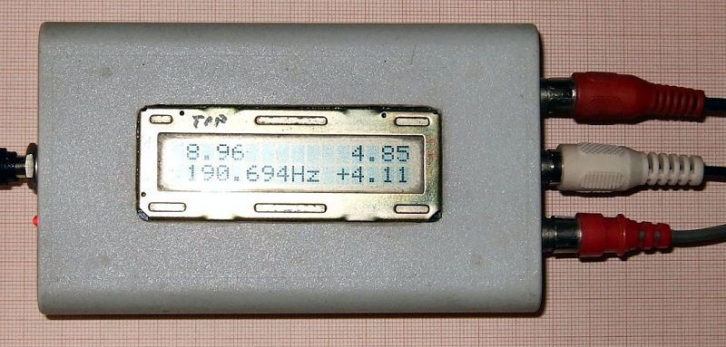
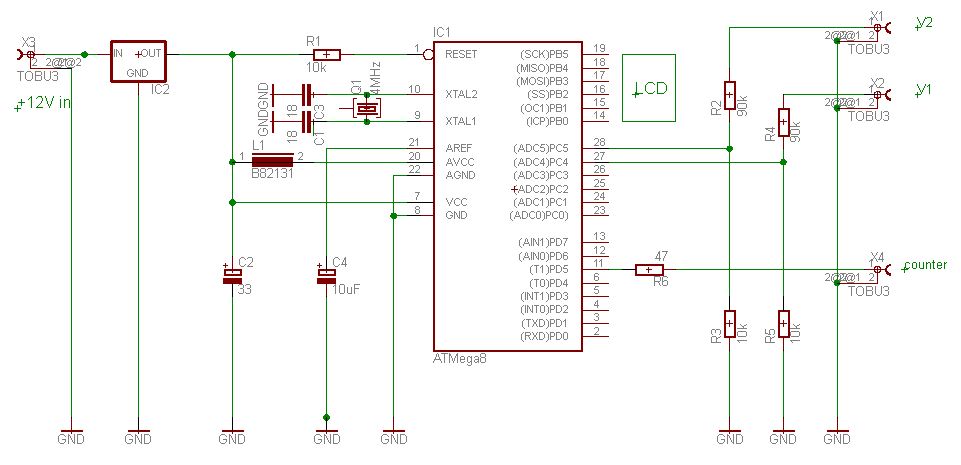
Gelegentlich muss man mehr als eine Spannung messen, vielleicht auch noch die Frequenz. Dann wird es schnell voll auf dem Arbeitstisch. Dagegen hilft dieses Multimeter mit dem ATMega8, es misst gleichzeitig zwei Spannungen V1 und V2 von 0 bis 26 Volt und zeigt auch die Differenz an: V1 - V2 rechts unten. Der Eingangswiderstand beträgt 100 kOhm. Parallel dazu arbeitet ein Frequenzzähler mit einer festen gate time von 1 Sekunde, die Timer2 erzeugt, und zeigt das Ergebnis in Hz unten links. Der Zähler geht bis ca. 1 MHz mit dem 4 MHz Quarz, bei 1 MHz zählt er 7 Hz zu wenig, das könnte man mit den Kondensatoren am Quarz trimmen, wenn es genauer werden soll. Es wird mit einem Steckernetzteil betrieben, ist im Prinzip also potentialfrei, die Masse der drei Eingänge ist aber miteinander verbunden.Ein schnelles Projekt für Regentage und es hält den Arbeitstisch frei.
Download: DVM_LCD4T.zip
'***************************************************************************
' ATMega8 LCD digital voltmeter GS 2013
' GS 3-2011, updated 2-2014
'
' 2 voltmeters , 0 - 26 V, displays difference V1 - V2
' measures Frequency with 1 sec gate time by T2, input at PD5
' display updated every second
'
' 4 ADC readings channel 4 5, Reference = internal (2.62 V)
' 10k/90k divider ADC channels
' calibrate factor: volts / ADC count, 0.02598 Volt/Count
'
' LCD display:
' 1234567890123456
' ----------------
' 12.00      01.00
'    1.000Hz+11.00
' ----------------
'
'  This program is free software; you can redistribute it and/or
'  modify it under the terms of the GNU General Public License.
'  This program is distributed in the hope that it will be useful,
'  but WITHOUT ANY WARRANTY;
'
'***************************************************************************
'              ATMega8 PDIP
'
'     (RESET)  PC6 1     28 PC5 (ADC5/SCL)
'       (RXD)  PD0 2     27 PC4 (ADC4/SDA)
'       (TXD)  PD1 3     26 PC3 (ADC3)
'       (INT0) PD2 4     25 PC2 (ADC2)
'       (INT1) PD3 5     24 PC1 (ADC1)
'    (XCK/T0)  PD4 6     23 PC0 (ADC0)
'              VCC 7     22 GND
'              GND 8     21 AREF
' (XTAL1/TOSC1)PB6 9     20 AVCC
' (XTAL2/TOSC2)PB7 10    19 PB5 (SCK)
'        (T1)  PD5 11    18 PB4 (MISO)
'      (AIN0)  PD6 12    17 PB3 (MOSI/OC2)
'      (AIN1)  PD7 13    16 PB2 (SS/OC1B)
'      (ICP1)  PB0 14    15 PB1 (OC1A)
'
'***************************************************************************
' Hardware: LCD-Display B port
' Pins ATMega8:
'  R/S  PortB 5  Lcd pin 4
'  E    PortB 4  Lcd pin 6
'  DB4  PortB 0  Lcd pin 11
'  DB5  PortB 1  Lcd data
'  DB6  PortB 2
'  DB7  PortB 3  Lcd pin 14

$regfile = "m8def.dat"
$crystal = 4000000
$hwstack = 32                                               ' default use 32 for the hardware stack
$swstack = 10                                               ' default use 10 for the SW stack
$framesize = 40                                             ' default use 40 for the frame space
$baud = 9600

'*********************************************************************

Ipulse Alias Portd.7
Mpulse Alias Portd.4
Rs232 Alias Pind.6

Const Calfactor0 = 2598                                     'calibrate
Const Calfactor1 = 2598                                     'calibrate

Const T2comp = 256 - 217                                    '18 Hz T2

Dim I As Byte
Dim N As Byte
Dim Dispcnt As Byte                                         'display counter
Dim Icnt As Byte                                            'ISR counter
Dim T1ovfcnt As Byte                                        'ISR ovf counter
Dim Cntflag As Byte                                         'ISR Cntflag

Dim Seconds As Byte
Dim Minutes As Byte
Dim Hours As Byte
Dim W As Word
Dim Ad As Integer
Dim Adch0 As Long
Dim Adch1 As Long
Dim Frequency As Long

Dim S As String * 10
Dim S1 As String * 6
Dim S2 As String * 6
Dim S3 As String * 6


'*********************************************************************
Config Lcd = 16 * 2
Config Lcdpin = Pin , Db4 = Portb.0 , Db5 = Portb.1 , Db6 = Portb.2 , Db7 = Portb.3 , E = Portb.4 , Rs = Portb.5

Ddrb = &B00111111
Portb = &B00000000

Ddrc = &B00001000
Portc = &B00000000
'Didr0 = &B00000111                                          'ch1 & 2 & 3 M48 only

Ddrd = &B10011110
Portd = &B11011111

Config Adc = Single , Prescaler = Auto , Reference = Internal       '2.62 V
Start Adc

' Config Timer1
Config Timer1 = Counter , Edge = Rising
Enable Ovf1
On Ovf1 T1ovf
Enable Timer1

' Config Timer2
Config Timer2 = Timer , Prescale = 1024
Tcnt2 = T2comp
Enable Ovf2
On Ovf2 T2ovf2

Enable Interrupts

'*********************************************************************
Lcd "Gerds DVM V4"
Wait 2
Cls
Cursor Off

Start Timer2
Start Timer1
Frequency = 12345
Cntflag = 1

Do

' measure voltage and frequency loop

  If Dispcnt = 1 Then                                       '1 s
      Dispcnt = 0                                           ' update display
      Stop Timer1
      'Tccr1b = 0
      Frequency = 65536 * T1ovfcnt
      Frequency = Tcnt1 + Frequency
      Tcnt1 = 0
      T1ovfcnt = 0

      Start Timer1
      'Tccr1b = &B00000111

      S3 = Str(frequency)
      S3 = Format(s3 , "    .000")
      S3 = S3 + "Hz "
      Mpulse = 1

      W = 0
      Adch0 = 0                                             ' V Getadc(4)
      For N = 1 To 4                                        'get ch 4
          W = Getadc(4)
          Adch0 = Adch0 + W
      Next N
      Shift Adch0 , Right , 2                               'div 4
      Adch0 = Adch0 * Calfactor0                            'volt/count, calibrate
      Adch0 = Adch0 / 1000
      S1 = Str(adch0)
      S1 = Format(s1 , " 0.00")
      'S1 = S1 + "V1"


      W = 0
      Adch1 = 0                                             ' V Getadc(5)
      For N = 1 To 4                                        'get ch 5
          W = Getadc(5)
          Adch1 = Adch1 + W
      Next N
      Shift Adch1 , Right , 2                               'div 4
      Adch1 = Adch1 * Calfactor1                            'volt/count, calibrate
      Adch1 = Adch1 / 1000
      S2 = Str(adch1)
      S2 = Format(s2 , " 0.00")
      'S2 = S2 + "V2"

      Ad = Adch0 - Adch1
      S = Str(ad)
      S = Format(s , "+0.00")

      Mpulse = 0

      Home Upper
      'Lcd "                "
      Locate 1 , 1
      Lcd S1
      Locate 1 , 12
      Lcd S2
      Locate 2 , 1
      Lcd S3
      If Len(s) = 6 Then
       Locate 2 , 11
      Else
       Locate 2 , 12
      End If
      Lcd S

      If Rs232 = 0 Then                                     'send data
        S = S1 + ";" + S2 + ";" + S3
        Print S
      End If

   End If                                                   'if dispcnt

Loop                                                        ' do again

'*********************************************************************

T2ovf2:                                                     'interrupt 18 Hz

   Ipulse = 1
   Tcnt2 = T2comp                                           ' reload T2
   Incr Icnt
   If Icnt = 18 Then                                        '1 sec
    Dispcnt = 1
    Icnt = 0                                                '1 second
    Incr Seconds
    If Seconds = 60 Then
        Seconds = 0 : Incr Minutes
    End If
    If Minutes = 60 Then
        Minutes = 0 : Incr Hours
    End If
    If Hours = 24 Then
       Hours = 0
    End If
'    S1 = Str(hours)
'    S2 = Str(minutes)
'    S3 = Str(seconds)
'    S = Format(s2 , "00") + ":" + Format(s3 , "00")
    'S = Format(s1 , "00") + ":" + Format(s2 , "00") + ":" + Format(s3 , "00")
'    Locate 2 , 11
'    Lcd S

   End If                                                   'Icnt
   Ipulse = 0

Return                                                      'reti

T1ovf:
   Incr T1ovfcnt
Return

End

'*********************************************************************