
Variable Duty Cycle Pulse Generator with ATTiny45
A simple pulse generator with a variable duty cycle and frequency is often useful in the lab to trigger or test other devices, e.g a servo with a frequency of 50 Hz and pulses between 1 and 2 ms. This is where the project started but for reasons we see later this idea was good but just not in this case.
The result however turned out to be a quite useable pulse generator with a frequency range from 10 MHz to 1 Hz in 30 overlapping ranges.
How is it done? From the Atmel datasheet we see that the duty cycle of Timer1 is basically D = (OCR1A+1) / (OCR1C+1). The PWM frequency is fpwm = 1 / (OCR1C+1). So the duty cycle D = fpwm * (OCR1A+1). This is calculated in the Basic program. We can set the frequency and keep the duty cycle constant at e.g 50% or any other percentage when the frequency is changed. The duty cycle D scale is linear but the frequency scale is not linear, bad luck it's hyperbolic as with most analog frequency generators, so the upper convenient frequency setting is at about 1 MHz. The frequency and duty cycle are set independently by reading 2 potentiometers with 2 ADC in a loop.
The controller uses an internal 8Mhz system clock (unprogram fuse CKDIV8) and also a fast PLL clock for Timer1 at 8 times the system clock. The PLL must be enabled and takes some time to lock, then Timer1 can run on a 64 MHz clock frequency. It takes now 1 pushbutton to toggle between PLL clock and system clock, one more pushbutton walks through the Timer1 prescaler values between 1 and 15 and back to 1 and so on. The main program is in Basic and the part dealing with the PLL is in assembler.
You would definitely need a scope or a frequency counter to know where you are, no pins left to display anything.
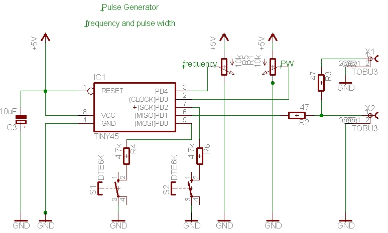
The circuit diagram, low parts count: 2 potentiometers, 2 pushbuttons 1 C and some resistors
Below is shown how it could be done in a small box with the tiny perfboard for the controller.
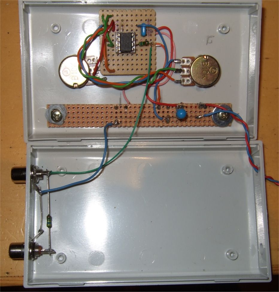
The final box, above the controller board and the strip below holds the pushbuttons in place. Needs an external 5V power supply.
It's digital and it's 8 bit pwm so it has some granularity when you turn the potentiometers which may be a limitation or not, depends on the application. As an example, with the system clock and clock/2048 for the prescaler the Timer1 will then get one clock pulse every 512 usec, that is the limit for the resolution, in other words, the duty cycle step witdh is 512 usec in this case. No way to get a 1 usec pulse width at a frequency of 50 Hz.
Anyway, I like this easy little thing. It can be used to control the speed of a DC motor (with a driver FET) or dim a led or what else you can think of.
download PulseG4.bas
This program is distributed in the hope that it will be useful but WITHOUT
ANY WARRANTY;
References
Atmel datasheet ATtiny45
Bascom Basic Compiler
		PLL clock	OCR1C		OCR1C		OCR1C		OCR1C		OCR1C		OCR1C		OCR1C
Presc	Ck/n	64.000.000,0	3		32		64		128		192		224		256
		toggle
1	1	32.000.000,0	10.666.666,7	1.000.000,0	500.000,0	250.000,0	166.666,7	142.857,1	125.000,0
2	2	16.000.000,0	5.333.333,3	500.000,0	250.000,0	125.000,0	83.333,3	71.428,6	62.500,0
3	4	8.000.000,0	2.666.666,7	250.000,0	125.000,0	62.500,0	41.666,7	35.714,3	31.250,0
4	8	4.000.000,0	1.333.333,3	125.000,0	62.500,0	31.250,0	20.833,3	17.857,1	15.625,0
5	16	2.000.000,0	666.666,7	62.500,0	31.250,0	15.625,0	10.416,7	8.928,6		7.812,5
6	32	1.000.000,0	333.333,3	31.250,0	15.625,0	7.812,5		5.208,3		4.464,3		3.906,3
7	64	500.000,0	166.666,7	15.625,0	7.812,5		3.906,3		2.604,2		2.232,1		1.953,1
8	128	250.000,0	83.333,3	7.812,5		3.906,3		1.953,1		1.302,1		1.116,1		976,6
9	256	125.000,0	41.666,7	3.906,3		1.953,1		976,6		651,0		558,0		488,3
10	512	62.500,0	20.833,3	1.953,1		976,6		488,3		325,5		279,0		244,1
11	1024	31.250,0	10.416,7	976,6		488,3		244,1		162,8		139,5		122,1
12	2048	15.625,0	5.208,3		488,3		244,1		122,1		81,4		69,8		61,0
13	4096	7.812,5		2.604,2		244,1		122,1		61,0		40,7		34,9		30,5
14	8192	3.906,3		1.302,1		122,1		61,0		30,5		20,3		17,4		15,3
15	16384	1.953,1		651,0		61,0		30,5		15,3		10,2		8,7		7,6

		System clock	OCR1C		OCR1C		OCR1C		OCR1C		OCR1C		OCR1C		OCR1C
Pre	Ck/n	8.000.000,0	3		32		64		128		192		224		256
		toggle
1	1	4.000.000,0	1.333.333,3	125.000,0	62.500,0	31.250,0	20.833,3	17.857,1	15.625,0
2	2	2.000.000,0	666.666,7	62.500,0	31.250,0	15.625,0	10.416,7	8.928,6		7.812,5
3	4	1.000.000,0	333.333,3	31.250,0	15.625,0	7.812,5		5.208,3		4.464,3		3.906,3
4	8	500.000,0	166.666,7	15.625,0	7.812,5		3.906,3		2.604,2		2.232,1		1.953,1
5	16	250.000,0	83.333,3	7.812,5		3.906,3		1.953,1		1.302,1		1.116,1		976,6
6	32	125.000,0	41.666,7	3.906,3		1.953,1		976,6		651,0		558,0		488,3
7	64	62.500,0	20.833,3	1.953,1		976,6		488,3		325,5		279,0		244,1
8	128	31.250,0	10.416,7	976,6		488,3		244,1		162,8		139,5		122,1
9	256	15.625,0	5.208,3		488,3		244,1		122,1		81,4		69,8		61,0
10	512	7.812,5		2.604,2		244,1		122,1		61,0		40,7		34,9		30,5
11	1024	3.906,3		1.302,1		122,1		61,0		30,5		20,3		17,4		15,3
12	2048	1.953,1		651,0		61,0		30,5		15,3		10,2		8,7		7,6
13	4096	976,6		325,5		30,5		15,3		7,6		5,1		4,4		3,8
14	8192	488,3		162,8		15,3		7,6		3,8		2,5		2,2		1,9
'***************************************************************************
'*
'* 	Title  : AT45 pulse generator
'*	independent setting of frequency and pulse width 0..100%
'*	frequency range: 10.6 MHz to 1.1 Hz
'*
'*          Pinb.2 button Toggle T1 clock source
'*          Pinb.0 button inc prescaler 1..15, no interrupt used
'*          Pinb.3 input poti 10k set frequency
'*          Pinb.4 input poti 10k set pulse width
'*          Pinb.1 output OCR1A frequency
'*
'* fpwm=fck/(OCR1C+1), Pw=Ocr1a -> Freq*Pw=fck*Ocr1a/(OCR1C+1), ratio
'*
'* program code  : BASCOM AVR basic
'* Last updated  : GS 4-2012
'* Target  :       ATtiny45
'*
'***************************************************************************
'  This program is free software; you can redistribute it and/or
'  modify it under the terms of the GNU General Public License.
'  This program is distributed in the hope that it will be useful,
'  but WITHOUT ANY WARRANTY;
'***************************************************************************
'
'   				ATtiny45 dip
'(PCINT5/RESET/ADC0/dW)         PB5  VCC
'(PCINT3/XTAL1/CLKI/OC1B/ADC3)  PB3  PB2 (SCK/USCK/SCL/ADC1/T0/INT0/PCINT2)
'(PCINT4/XTAL2/CLKO/OC1B/ADC2)  PB4  PB1 (MISO/DO/AIN1/OC0B/OC1A/PCINT1)
'                               GND  PB0 (MOSI/DI/SDA/AIN0/OC0A/OC1A/AREF/PCINT0)
'
';***************************************************************************

$regfile = "ATtiny45.DAT"
$crystal = 8000000
$hwstack = 32                                               ' default use 32 for the hardware stack
$swstack = 10                                               'default use 10 for the SW stack
$framesize = 20                                             'default use 40 for the frame

Dim I As Byte
Dim Prescc1 As Byte
Dim Channel As Byte
Dim W As Word
Dim Freq As Word
Dim Pw As Word


Ddrb = &B00000010
Portb = &B00000101                                          'pullup PB0,2

'*********************************************************************


$asm                                                        ' turn on PLL
  ldi  R24, &B00000010                                      '; Enable PLL (1<<PLLE)
  out PLLCSR, R24
waitPLL:
  in R24, PLLCSR                                           '; Wait for PLL to lock (approx. 100ms)
  sbrs  R24, PLOCK
  rjmp  waitPLL

  in R24, PLLCSR                                           '; Set PLL as clock source
  ldi R25,&B00000100                                        ';(1<<PCKE)
  or R24, R25
  Out Pllcsr , R24
$end Asm


Didr0 = &B00011000
Config Adc = Single , Prescaler = Auto , Reference = Avcc
Start Adc


Tccr1 = &B11100011                                          'CTC, pwm, clr
' B11100000 = 224 dec
Prescc1 = 3

Ocr1c = 199
Ocr1a = 100

'Start Timer1

Do                                                          'all in 1 loop

Debounce Pinb.2 , 0 , Togt1ck , Sub                         'Toggle T1 clock source
Debounce Pinb.0 , 0 , Incpre , Sub                          'increment prescaler

Channel = 2
Freq = 0
For I = 1 To 8
   W = Getadc(channel)
   Freq = Freq + W
Next I

Channel = 3
Pw = 0
For I = 1 To 8
   W = Getadc(channel)                                      '10 bit
   Pw = Pw + W
Next I

Freq = Freq / 32                                            'make 8 bit
Pw = Pw / 64
Pw = Pw * Freq
Pw = Pw / 128

If Pw = 0 Then Pw = 1
If Freq < 2 Then Freq = 2

Ocr1c = Freq
Ocr1a = Pw
' fpwm=fck/(OCR1C+1), Pw=Ocr1a -> Freq*Pw=fck*Ocr1a/(OCR1C+1), ratio

Loop

'********************************Sub*************************************

IncPre:
   Incr Prescc1                                             'inc prescaler
   If Prescc1 >= 16 Then Prescc1 = 1
   Tccr1 = 224 + Prescc1                                    'set prescaler
Return                                                      '


Togt1ck:                                                    'Toggle T1ck source
$asm                                                        ' turn on PLL
  in R24, PLLCSR
  sbrc R24, 2                                              '; PCKE not set
  rjmp dp1                                                  '; if set then clear
  sbr R24, 4                                               '; Set PLL as clock source
  out PLLCSR, R24
  rjmp dp2
Dp1:
   Cbr R24 , 4                                              '; Set system CK as clock source
  out PLLCSR, R24
Dp2:
$end Asm

Return