The antenna's construction has been improved to try and reduce
parasitic capacitances. The signal is now
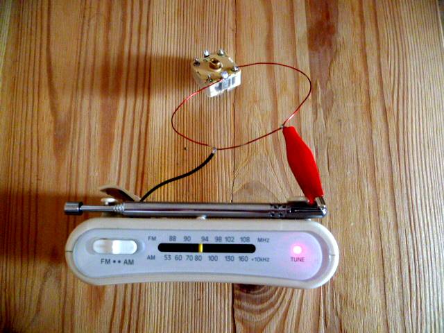
tapped across only part of the coil (3 cm).
This modification has increased the Q of the antenna and
improved the signal strength. One side of the antenna is clipped
to the receiver's battery terminal (ground), whilst the other side is
clipped to the telescopic rod.
This temporary arrangement allows the antenna to
be easily removed for experiment.
The antenna's tuning is now quite sharp. When tuned,
the signal strength is definitely better than
the telescopic rod. I hope a smaller
variable capacitor can be used in the next design. It may be
possible to fabricate the antenna on a PCB, which could be
fixed to the receiver. More areas for experiment:)Here is a video showing
the operation of my FM loop antenna
http://www.youtube.com/watch?v=NK03gUCo8_M The inductance was calculated using this
equation
http://www.qsl.net/in3otd/ind2calc.html


